How to Add a Crystal in Electronic Siren Circuit
Posted: Thu Jun 08, 2017 7:50 pm
Good day,all
I have finished a electronic siren circuit which based on three transistors.Please look at the following circuit diagram:
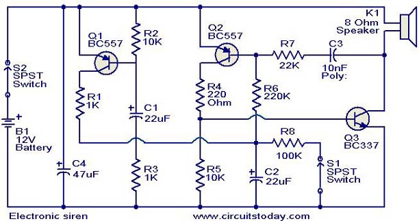
This electronic siren circuit I found on internet is based on a complementary transistor pair consistin of Q2 & Q3 (BC557 & BC 37) wired as an astable multivibrator oscillator,which directly drives the speaker.The transistor Q1 is used to provide a full charge on capacitor C2 when power is turned ON. When push button switch S1 is pressed , the capacitor C2 slowly discharges through resistor R8.This makes the circuit to oscillate at a low frequency that increases to a high frequency and kept indefinitely as the capacitor is fully discharged. When the switch P1 is released, the output frequency decreases slowly as C2 is charged to the positive voltage through resistance R6 and the Base-Emitter junction of tramsistor Q2. When C2 is fully charged to the positive battery voltage the circuit stops oscillating.Well,I use a 12V battery to power the circuit and the switch S1 to activate the alarm.
The BC557 datasheet: http://www.kynix.com/uploadfiles/pdf/BC557.pdf
After finishing the circuit,it can work.However,I want to ask that how do I add a crystal to stabilise the frequency when battery voltage drops?
I am just interesting in this circuit,I’m not professional. So please forgive me any foolish questions!
Thanks~
I have finished a electronic siren circuit which based on three transistors.Please look at the following circuit diagram:
This electronic siren circuit I found on internet is based on a complementary transistor pair consistin of Q2 & Q3 (BC557 & BC 37) wired as an astable multivibrator oscillator,which directly drives the speaker.The transistor Q1 is used to provide a full charge on capacitor C2 when power is turned ON. When push button switch S1 is pressed , the capacitor C2 slowly discharges through resistor R8.This makes the circuit to oscillate at a low frequency that increases to a high frequency and kept indefinitely as the capacitor is fully discharged. When the switch P1 is released, the output frequency decreases slowly as C2 is charged to the positive voltage through resistance R6 and the Base-Emitter junction of tramsistor Q2. When C2 is fully charged to the positive battery voltage the circuit stops oscillating.Well,I use a 12V battery to power the circuit and the switch S1 to activate the alarm.
The BC557 datasheet: http://www.kynix.com/uploadfiles/pdf/BC557.pdf
After finishing the circuit,it can work.However,I want to ask that how do I add a crystal to stabilise the frequency when battery voltage drops?
I am just interesting in this circuit,I’m not professional. So please forgive me any foolish questions!
Thanks~