Hi, first time here as you can see. I found the 2001A system analyzer in the forum and have that in hand. My problem is this analyzer would always start resetting after about 3-4 hours on, I always turned it off and let it cool down. Well the other night I forgot and left it on. In the morning it was dead. AC light comes on, nothing else. Scanning through the R2001A book, it appears to be quite a bit different than mine. My back panel has a fan,which is undoubtedly not up to the task, and the connections are in different places than shown in the A manual. The boards look different too. I'm wondering where to go with this. I've seen the R2001D manuals (CD) in ebay, but for about $75.
Anyone have a clue where to go from here? I've made a few preliminary measurements on the A3 board which appears to be a DC supply, looked for burned items in all the A2 through A6 boards and I don't see any burned items, I even went so far as to check diodes, transistors with the Fluke 189 and nothing appears out of the ordinary, but I'm shooting in the dark here.
A good manual would be a real help.
Ideas? thanks,
Dave
R2005D/HS problem
Moderator: Queue Moderator
Re: R2005D/HS problem
Digging into the R2001A manual and comparing it to my R2005D, they are nothing alike. The 2001A DC power supply module A1 takes up the space where the R2005D A2 through A6 reside. Does anyone know if a R2001D service manual would be appropriate for my monitor?
If anyone has the pin outs for the DC supply (4 pin) It would be helpful if I can see if the thing will run off DC and it's just an AC power supply problem. I traced pin 3 to +DC, 4 to chassis ground and 1 and 2 are tied together at one end of the DC fuse and the other end of the fuse goes to double wires which is attached to what appears to be the mother board ground, not chassis ground. So perhaps 1 and 2 are -DC and the fuse is connected in the low end of the DC feed? I don't want to burn this thing up any more than I already have.
Dave
Re: R2005D/HS problem
OK, I see I posted this in the wrong place. Sorry, and then I replied to it. Anyhow, I found this
1 - 13.6 VDC+
2 - 13.6 VDC+
3 - Charger output for battery pack
4 - Ground
Is this the same for the R2001D? It appears so, but want confirmation. I think I was confusing + with -.
Also the R2001A manual shows A1 where I have A2 through A6. Does anyone have a lead to a R2005D manual? The R2001A is lots different than mine.
Thanks,
Dave
-
Andy Corbin
- Posts: 158
- Joined: Tue Apr 19, 2005 3:46 pm
Re: R2005D/HS problem
You might try http://www.repeater-builder.com/motorol ... index.htmlDogT wrote:Hi, first time here as you can see. I found the 2001A system analyzer in the forum and have that in hand. My problem is this analyzer would always start resetting after about 3-4 hours on, I always turned it off and let it cool down. Well the other night I forgot and left it on. In the morning it was dead. AC light comes on, nothing else. Scanning through the R2001A book, it appears to be quite a bit different than mine. My back panel has a fan,which is undoubtedly not up to the task, and the connections are in different places than shown in the A manual. The boards look different too. I'm wondering where to go with this. I've seen the R2001D manuals (CD) in ebay, but for about $75.
Anyone have a clue where to go from here? I've made a few preliminary measurements on the A3 board which appears to be a DC supply, looked for burned items in all the A2 through A6 boards and I don't see any burned items, I even went so far as to check diodes, transistors with the Fluke 189 and nothing appears out of the ordinary, but I'm shooting in the dark here.
A good manual would be a real help.
Ideas? thanks,
Dave
See if any of the manuals there are of help.
Andy
Re: R2005D/HS problem
Yeah, I already found that and the closest one is the R2001/2 but no banana. Mine is much different. Now that I've figured the DC input I'll try that and see if it works.
Dave
Dave
Re: R2005D/HS problem
The power supply in the D series is much different ( and much better ) than the previous 2000 Series.
Normally like most of the electronics these days it starts with the capacitor failures.
Hopefully you have a meter that can test for the large cap values and I would go through the four plug in power supply assemblies toward the rear under the separate cover with the high voltage warning. Would also check for shorted switch transistors on the rar right board from the front. It has two sets ...one for DC and one for AC.
Hopefully the set powers up on DC ( Pin 1 is A+ ...ground is chassis or pin 3 )
Usually the sellers on will take offers.
Re: R2005D/HS problem
So the D model DC input is different than the A model? I see on mine, DC pins 1 and 2 are connected together at the fuse, the other end of the fuse goes with double wires to a tie point on the motherboard that connects directly into A6 with 4 pins (4,5,6,7) and a large track from that pin. Pin 4 is chassis ground, and pin 3 goes to a MB track that connects to pin 12 of A3.
I would think looking at that, DC+ would be pins 1 and 2, DC- would be 4, don't know what pin 3 is.
Until I'm sure what I'm doing, I'm not doing anything. I ordered the D model CD.
I would think looking at that, DC+ would be pins 1 and 2, DC- would be 4, don't know what pin 3 is.
Until I'm sure what I'm doing, I'm not doing anything. I ordered the D model CD.
Re: R2005D/HS problem
The DC power pinout about is correct for all of the R2XXX series ....usually use 2 & 4 for power and ground
Re: R2005D/HS problem
Actually, Motorola used 1 & 2 because of the current amount when using the battery pack. The same pack was used in ALL the R2000 series (A through D) and the same pinout was also used in the R2200/2400 and R2600 series.jry wrote:The DC power pinout about is correct for all of the R2XXX series ....usually use 2 & 4 for power and ground
Dave
Re: R2005D/HS problem
OK, but jry says above pin 3 is 'ground or chassis'. I think he means pin 4, no? Pin 3 on my D model goes to pin 12 of A3, I traced it.
Anyhow, I've got a service manual coming one way or the other. The more I look the more it looks like an AC power failure, I get no voltages on A3 or A6 with AC input and the AC led on.
I'll report what I find.
Dave
N3DT
Anyhow, I've got a service manual coming one way or the other. The more I look the more it looks like an AC power failure, I get no voltages on A3 or A6 with AC input and the AC led on.
I'll report what I find.
Dave
N3DT
Re: R2005D/HS problem
Pin 3 is used to recharge the battery pack option. Try checking the test points on the A5 board with an ohm meter to chassis ground.One of them (#8 IIRC) is ground and one of them will give a reading around 50 ohms. The rest should be fairly high.DogT wrote:OK, but jry says above pin 3 is 'ground or chassis'. I think he means pin 4, no? Pin 3 on my D model goes to pin 12 of A3, I traced it.
Dave
N3DT
Dave
Re: R2005D/HS problem
Yes, I checked out A5 visually and with the Fluke diode tests and one of the TP's is ground, it's connected to an electrolytic, ground side, chassis. But there are absolutely no voltages on the other TP's. Checking with the ohms, 1-4 are around 200Ω, 5 is short to ground and 6,7 are real high Ω, if the TP's are in the same relation as the A6 board which is marked. On A6 I pulled the FET transistors BUZ42 (looks like the AC switchers) and they appear to be ok with my analog meter test (I have an old large scale Simpson as well as the Fluke 189), but real hard to tell. No dead shorts in them.
More to come. I can't wait to get this thing working again, I have a couple of R390A's to work on and this thing is taking up all my bench space.
More to come. I can't wait to get this thing working again, I have a couple of R390A's to work on and this thing is taking up all my bench space.
Re: R2005D/HS problem
You have a short. Those test points (I don't remember the order) are for +5, -5, +15, -15, +33, +100 & -100 volts. The 100 volt supplies are only used on the scope amp board A2. Put your ohm meter on the shorted TP5 & pull the boards out one at a time to narrow down the problem.
Dave
Re: R2005D/HS problem
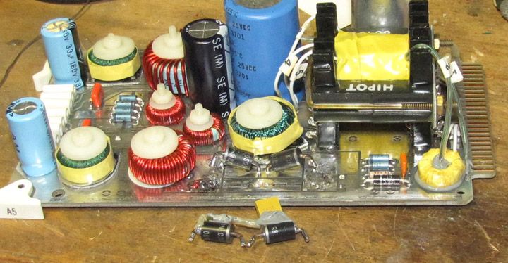
I thought A5 TP5 was connected to a cap on the ground side, but I pulled the cap and no, the trace goes under it to a coil (toroid). Found a shorted 50SQ100 diode, one of a full wave bridge circuit and it has a capacitor and small value resistor, 6.9Ω, connected across the anode ends of 2 of them. Wonder if I should just go ahead and replace all 4 of them, I can get them at Jameco, but I have to buy 5. But what else may be wrong? It's the diode with the cap glued to it. I don't know if this forum supports pic links, but here goes.
Re: R2005D/HS problem
I got the CD manual tonight and looking through it quickly, it appears that the control board A6 will shut down the power supply with shorts or high voltages. This is a good sign to me. It just may be that the shorted diode is the problem and hopefully when I get it fixed the thing will come back on. All I can do is try. I reckon the next thing to try is the DC input. Manual from 'southern cross' looks good and readable, if a bit pricy.
Glad the pic worked.
Glad the pic worked.
Re: R2005D/HS problem
Looks like you have probably found your problem. The picture also reminded me of another typical "D" model problem on the LVPS boards. The (physically) large capacitors have a tendency to break loose from the solder joints, especially the ones on the A3 & A6 boards. Just wiggle them slightly while looking at the solder side & if necessary, reheat the joint.
Dave
Re: R2005D/HS problem
I just ordered the diodes from Mouser. Jameco had a wait on them plus Mouser will ship USPS priority so I should have them Monday or Tuesday. I'll check out the capacitors while I'm in there.
Re: R2005D/HS problem
Replaced all 4 diodes although only one was shorted. Same problem. AC light is on, but doesn't go on. No voltages on the A5 TPs, but the short is gone. The saga continues.
Re: R2005D/HS problem
Checked voltages on A4 TP and they are good. Hard to check U2 pin 16 for voltage, I may have to build an extension card. Anyone know where to get a same sized card I can hack up? Or I could solder an extension wire on it temp. I'm afraid there's something wrong with A4 and it might be one of the ICs and it's turning things off.
Anyhow, now the oven light now goes on, but no other indication. I didn't see any interlock on the covers or anywhere else?
Anyhow, now the oven light now goes on, but no other indication. I didn't see any interlock on the covers or anywhere else?
Re: R2005D/HS problem
On A4, all the TP voltages are good and I stuffed a little wire under pin 16 U2 A4 and there is +5VDC there, so all the voltages check out good on A4. Still nothing. Did a search on A4 for bad diodes, shorts, nothing found. The search goes on. I'll have to start checking voltages on the mother board side of A4 and see if I can find anything there.
Re: R2005D/HS problem
I've been digging through the schematics and the block diagrams, correcting the mistakes in them, but so far finding no problems but the voltages to the Control board not there. I'm sure it's a problem in the power circuits and the Control Board is very suspect, but very hard to trouble shoot. All the power supply boards are interconnected and the main block diagram doesn't show everything. Right now I'm working on the Switcher Board to see if I can find anything there.
I could sure use some help.
I could sure use some help.
Re: R2005D/HS problem
I tried the DC input today (Dec 2) and the relay kicks in and the BAT light lights, but when I put the power switch in DC position, the AC and Oven light come on for about a half second and then go off. Monitoring the current input, there's an initial flow when I connect the DC supply, and also when I switch it into DC, but current flow goes to 0 in both cases. So what ever it is, it must be associated with both AC and DC circuits. I still get the feeling the Control board is shutting things down.
Re: R2005D/HS problem
I'm just not getting anywhere with this thing. All the voltages for A4 are correct per the trouble guide, but I get nothing out of the AC or DC drive circuits, and that means the Low Voltage board A5 will not work, so there are no voltages all over the place.
I'm pretty sure it's something on the Control board shutting things down, but to trouble shoot? I may have to make an extender board. It's hard trouble shooting a board with no voltages on it.
I'm pretty sure it's something on the Control board shutting things down, but to trouble shoot? I may have to make an extender board. It's hard trouble shooting a board with no voltages on it.
Re: R2005D/HS problem
normally I just tack a wire on the point or points I want to look at if I am missing the extender card. Works well for low frequency and DC measurements.
Would look at the PWM IC and see if it is getting enabled /starting
May be getting turned off by either a false or real over current or over voltage on an output
Would stick with DC powering the unit so you can more easily see the input current and less high voltage running around.
You should see some spikein current as the initial filter caps charge. if you can scope one of the outputs and see if the power supply is even trying to start and then getting shutdown by a fault.
Goof luck ...switching supplies can be a real pain ...often I have to open the loop ( feedback voltage) and insert my own DC level to trouble shoot but that is only useful if you can operate the supply stand alone. In this case there is no way to extract or disconnect the power supply from the unit.
You may be wise to pull or dis-connect the assemblies until you get it sorted out. The off chance is you have a short some place. Not that tough but those card guides can be really tight on some units .
You can pop the ribbon cables to the RF I/O and reference oscillator on the bottom.
Good luck
Re: R2005D/HS problem
Yes, I've pulled all the other boards up so most things are disconnected except A15, which seems to need to be in for the power switch to work, and the power supply boards.
I did take the A4 board out and try to power it with 15V on the Freq std supply pin, and that powers most of the internal things including the PWM, but of course the voltages are not there for the voltage sense (+32), current sense, overvoltage lockout which should not matter, I added +5 for the loop filter from another power supply but I didn't have 32V for the AC voltage sense and without that the PWM is locked out and the AC/DC switch over is not energized which may not matter. If I can come up with another supply for the 32V, maybe I can see if the PWM is working, at least even on initial start up, but it sure looks like something is shutting the PWM off. Then there's -5V which does something for U4, the high voltage driver control.
I've been trying to figure out the SG3525A and it's voltages but am still confused about what 'shutdown' pin 10 and 'input' pin 2 want to see. It looks like pin 2 wants to see 0 because when I put +5 on the loop filter input, it drives pin 2 to ground. Pin 10, the shutdown is connected the AC/DC current sense and I'm not sure what I want to see on that pin. From reading it looks like high turns the PWM off and I've got +5 on that pin for some reason.
Then there's pin 8 soft start and lockout?
I'm still thinking about making an extender board, I could carve up a double sided board and solder on a 50 pin connector. Unless I can get A4 running off power supplies or wires tacked to the mother board and A4. That may be the next approach I take.
Re: R2005D/HS problem
I finally determined that U2-10, the shutdown, wants to be at 0V and is at 5V. So I traced it back to U8A-13 and then found U8A-8 is +5V. The truth table says with 5V on 8, 13 can never go low, so back to U5A which is just an inverter, so the input is low and that comes from either U6A, the AC over current comparator, or U6B, the DC over current comparator. It took me a while to determine how the inverting voltage comparator works, but it should be +5V out with less than 1.5V on the input with the ref at 1.5V (the AC side). So it looks like U6 is bad, actually all 4 of the outputs of U6 are low, so that's the culprit for now. I ordered all the chips plus spares on A6 I could from Mouser in case something else may be bad, and I'm also going to put any chip I replace in sockets. I have an LM339 (U6) but I'm going to wait until I get the socket to install it.
Wish me luck.
Dave
Wish me luck.
Dave
Re: R2005D/HS problem
It seems to take forever to get something posted here. Anyhow, I got A4 working on the bench with +14, +32 and the appropriate grounds. Everything on A4 seems to work correctly, by itself, I get driver output on AC and DC. I plug it in the MB with the rest of the PS boards and I get a spike on the AC driver outputs, but it goes right away. I'm sure something is still shutting down the A4 board, but I think I need to build an extender board to see what's shutting it down. At least I know what A4 needs to work with all the IC voltages now. Really hard to trouble shoot something when it turns itself off.
Re: R2005D/HS problem
I've narrowed it down to the A5 board. The A4 control board is shutting things down because of overcurrent. It looks like it may be T1 on A5, but I'm hoping it's something else. I've pulled all the diodes off the output of A5 T1. In the meantime I've blown the rectifiers on the A3 board by removing the overcurrent IC in A4 it looks like. I think I'm getting closer but we'll see when I get the A3 board working again.
Re: R2005D/HS problem
Looks like I've got it. Apparently when I replaced the bad diode in A5, I left a solder bridge across two other diodes, it took me a while to find it, and in the mean time, I pulled the overcurrent protection IC (U8) on A4 and wiped out the AC switching FETs on A6. In the meantime, I found the other short in the A5 board, replaced the AC switching FETs and now it appears to be working. I'm going to leave it on for a while before I put the covers back on.
So it appears all along it was an overcurrent shutdown caused by diode shorts in the LVPS A5. Trouble is the only way you can see it's in overcurrent protection mode is to look at U8 pin 13 or U2 pin 10 (connected) on A4 and if it's at 5V, it's shutting down the PWM. Unfortunately you can't see, or at least I couldn't see, the clock pulse that was making U8-13 go hi . It should be available on A4 TP1, but I never saw anything there, even on a scope.
I know more than I want to know about A4, the control board now.
Woo, Hoo.