Page 1 of 1
spectra command board plug
Posted: Thu Mar 22, 2007 10:15 pm
by ke7joi
gentlemen
can someone help me with which pin to tie together the get the following signals out the rear option connection on my 900 mid power spectra
tx audio
rx audio
tx key
det audio

Posted: Fri Mar 23, 2007 1:17 am
by Will
The male connector is for the DTMF Decoder or HearClear board. Not used in most applications.
Now to the the other part,
tx audio Is allready there, pin 15
rx audio needs a capacitor added on the control interface board
comes out on pin 12
tx key Is on pin 13
det audio Is on pin 11
spectra command board plug
Posted: Fri Mar 23, 2007 3:06 am
by ke7joi
will my 900 spectra has both hearclear and dtmf on the command board it is an E model. the radio you are looking at is my high power VHF spectra for example only. I was told that that duel in line plug was for option setup on the rear connector and also the programing plug on the high power units.
Posted: Fri Mar 23, 2007 11:21 am
by Mike B
The plug you circled is P501. Here is the P501 connector pin out:
http://www.open.org/~blenderm/spectra/b ... tml#spp501
P501 is documented in the 68P80101W33 detailed service manual or in the 68P80102W61 detailed service manual.
http://www.open.org/~blenderm/spectra/manualss.html
spectra option connector
Posted: Fri Mar 23, 2007 11:58 am
by ke7joi
thank you Mike B
can you tell me what and where I need to jumper to get those signals out the rear connector on my 900 spectra ?
Posted: Sat Mar 24, 2007 4:02 pm
by Mike B
The rear DB-15 is supposed to be this standard pin out:
http://www.open.org/~blenderm/spectra/i ... #j2dashrem
If your radio was an SP or the last owner made changes, then you need to track down a bunch of option jumpers on the command board for whatever signals are different. The detailed service manual for whatever part number of command board you have is essential. Have you even checked your current DB-15 pin out yet?
Other than a few pins that are already shared, there are no jumpers to route the other P501 pins to the rear DB-15 pins. In order to bring out any desired P501 pin to the rear DB-15 connector, you will have to make totally custom jumper wires that will have to reach across the command board and probably remove option jumpers to remove the existing connection to the DB-15 pin. Again, the correct manual would be required for this.
You will also have to figure out how to add the capacitor and hook the Rx audio to pin 12. Will might have better directions for that.
Be very careful, I also have an ACME disintegrater gun!

Re: spectra command board plug
Posted: Sat Mar 24, 2007 6:25 pm
by Will
ke7joi wrote:<will my 900 spectra is an E model>.
OK, you are talking the E model Spectra? The P501 connector on the command board is STILL for the encryption board.
I think we need the part number on the Command board.
spectra command board
Posted: Sat Mar 24, 2007 7:32 pm
by ke7joi
Will
this should help you. I just took it apart and it is not a e model but the picture should help also looked at thev interconnect board can I get all the signal out of J0006
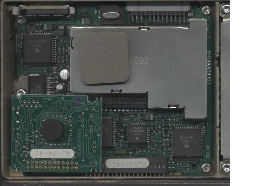
here is the front of the interconnect board
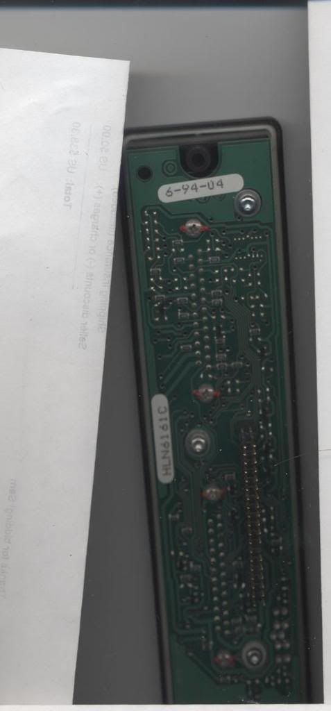
and here is the back
Posted: Mon Mar 26, 2007 12:04 am
by Will
Yup, that is a good ole Spectra.
All the connections you need are already on both DB25 connectors....
In fact it looks like you just need a data transceiver, so just need a jumper to replace the control head and the connections you listed.
The connections are on Mikes site:
Pin 6 Filtered Audio RX
Pin 2 Sheild
Pin 9 Discr audio
Pin 10 Analog ground
Pin 11 Mic lo
Pin 12 Mic hi
Pin 1 PTT
Pins 20 and 22 jumpered +12 volts
spectra interconnect board
Posted: Mon Mar 26, 2007 1:41 am
by ke7joi
Will
thank you for the info the only problem is that if you look at the interconnect digram below you will see that some of the signals I need are not pined through I have found the ptt Jumper #JU605.
I have not been able to locate jumpers JU606,JU607,JU608 and JU609
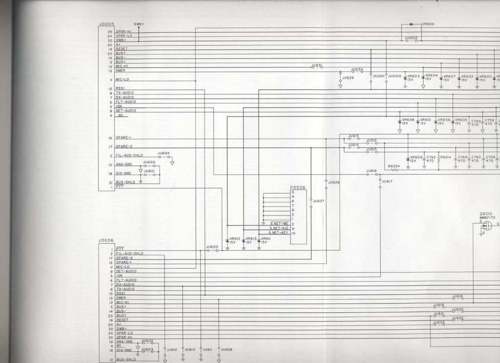
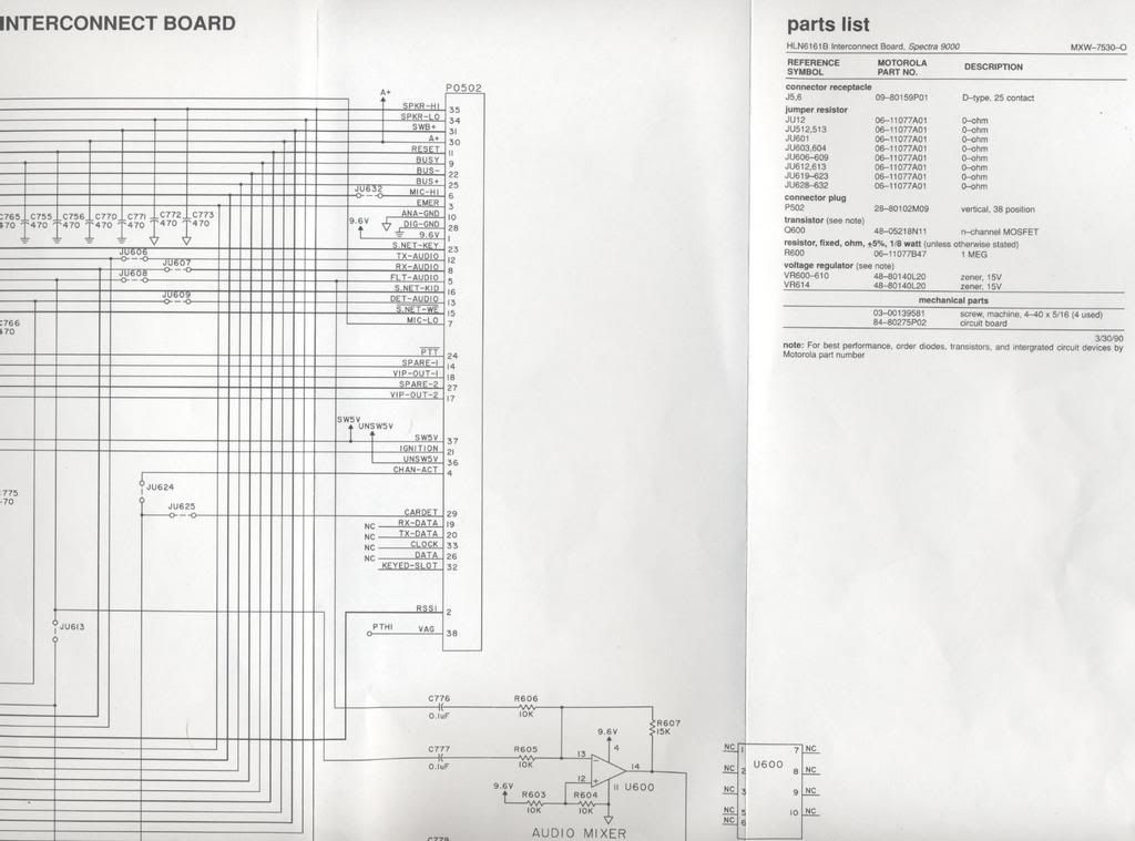
so what I really need now is a digram of the board that tells me what jumper is what as the board has no identifiers on it.
Also I guess I should explane what I am tring to do here I my intent is to use the spectra a cross band repeater part of the time to allow me to walk around with my 900ht and talk on 2 meter I have solved most of my problems all I need now is to get all the signals pined through the interconnect board the rest is easy.
Posted: Mon Mar 26, 2007 3:35 pm
by Will
Joel, Unless someone butchered the interconnect board, all the signals you need should be on the two DB25 F connectors.
If you still have a problem, there are many "sub" versions with different jumpers you may send me the Interconnect board and I can check it in one of my test setups.
Posted: Mon Mar 26, 2007 4:22 pm
by ke7joi
will
my interconnect board does not seem to have all of the pins tied through do you have a picture of the board with the jumpers identified on it I have checked with an ohm meter an the signals are not pined through all the jumpers if i had a picture I could fix it myself as I have good electrontics skills.
help