Page 1 of 1
Systems Saber half deaf after dropping it to the ground
Posted: Sat Oct 04, 2008 2:49 am
by oh2lna
So I accidentally dropped my Systems Saber (model 1) to the ground while validating a rapid transit ticket. No visible signs of injury, but I cannot access the local repeaters anymore.
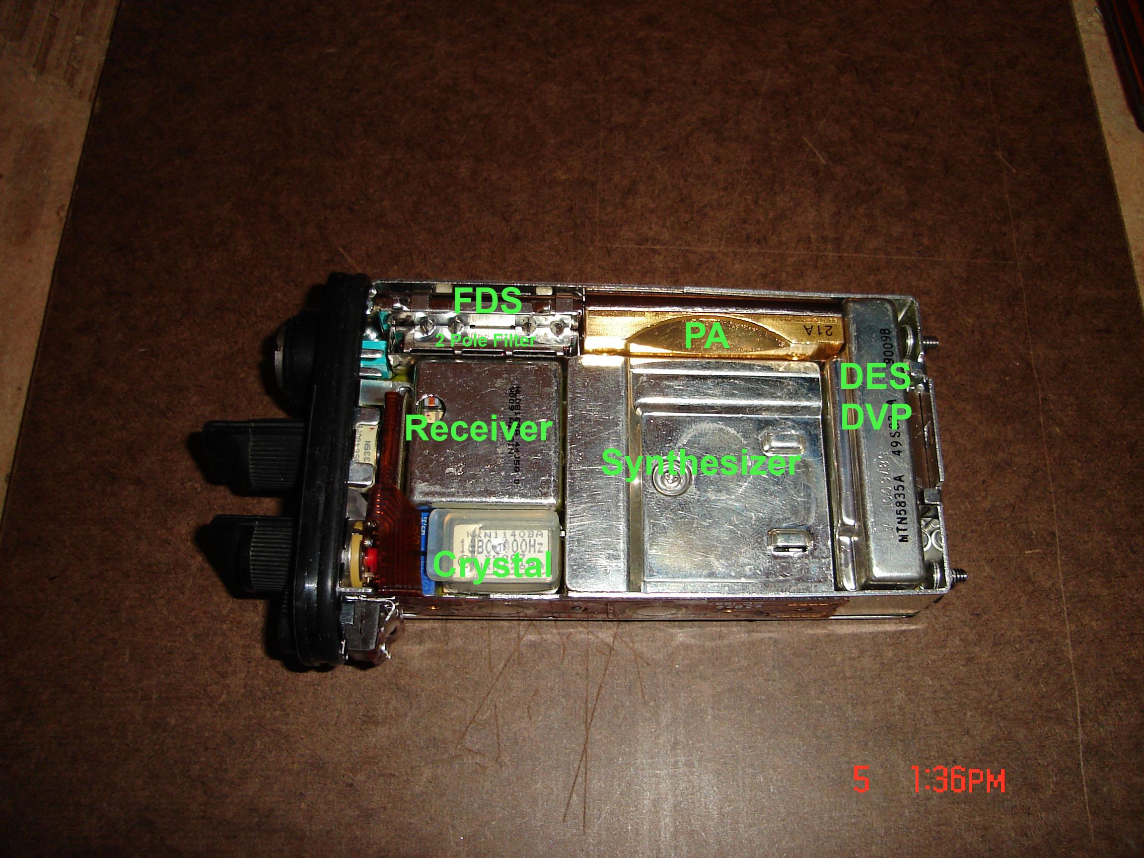
[Photo from the actual dropped Saber.]
Is there a document out there anywhere that would show what things should look like inside the Systems Saber model one, and most importantly where all those screws were intended to be. I didn't document the order and places well enough while disassembling it and I've got a couple of "left overs" now. Also, somewhere between
the FDS and the receiver there was a small ___..___ -shaped metal plate that doesn't show in the photo. What should its proper place be?
The radio seems to work at some level, since I was capable of receiving and transmitting to/from another radio from a couple of feets away, but everything else that goes beyond that, it's a no show now. It's like the connection to the antenna was lost or something similar like that. Any hints where to look for contact failures?
Re: Systems Saber half deaf after dropping it to the ground
Posted: Sat Oct 04, 2008 9:14 pm
by WB6NVH
I seem to recall that the antenna connection setup on the Saber is rather easily broken. Someone here with more experience than I on this radio should be able to comment better than I can.
Geoff
WB6NVH
Re: Systems Saber half deaf after dropping it to the ground
Posted: Sun Oct 05, 2008 1:17 am
by oh2lna
No similar documents for the Systems Saber, like the Batdude's Guide
pp. 50-69 for the Astro Digital Saber? I'm having difficulty figuring out on how to disassemble the antenna connector area any further than this:

Re: Systems Saber half deaf after dropping it to the ground
Posted: Sun Oct 05, 2008 9:03 pm
by AEC
Your Saber is NOT anywhere close to any Astro Saber as it is incapable of that operation, and also, the construction are absolutely different in every extreme.
That said, it appears you removed just about every module from the radio, and it looks like it's a UHF radio.
All modules MUST be firmly seated in their respective locations.
From top left, you have the keyboard/front cover ribbon flex along the frame, then the reference oscillator(16.8 Mhz.)(MUST be replaced the same way for pin #1 alignment in order to function)
On the right side of the frame, you have the low pass filter.
Upper center, the receiver module(two screws-offset).
The P.A module is installed on the lower right, and to its immediate left, is the synthesizer, which is held in place by two screws holding the rear cover inplace, just as the top left cover screw retains the external antenna ground 'tang' to the chassis.
If all modules are in their proper places, and the radio operates normally, I would first look at the reference oscillator and make sure it's ON 16.8 Mhz, as this is the main reference for the entire radio's RX and TX chain and is also working in unison with the VCO so the frequency tracks in a proper range.
Second, check the receiver module, it splits mid-case and the lower section holds the filter(rectangular shape with a red rubber isolation pad below it)
There are also ground fingers all around this module, internally, so note where they are on the module as you disassemble it.
Make sure there are no cracks in the ceramic filter as this will have detrimental effects on the reception of signals.
If you have access to a service monitor, or any kind of high quality test equipment, great, it will help you isolate most problems.
Aside from visible, physical damage, internal damage can be cracks in the circuit boards, broken leads on surface mounted devices, or with poor reception, bad PIN diodes that may be shorted, or open(with signal applied).
Since PIN diodes conduct upon being forward biased, they are easy to troubleshoot.
Sniff the RF circuits for dead oscillators, inspect the main board for hairline cracks with a high powered magnifying lens, and look for the usual physical damage as well as contact 'issues' with the antenna connection on the upper left of the board, it will be a small 'M' shaped contact that the antenna pin slides into, if this has widened only, simply squeeze the wire together and retest the receiver before making ANY adjustments to the receiver through RSS or the service menu.
I can not stress how important SAVING your codeplug is enough, you should always store a KNOWN GOOD codeplug of ALL your radios for future reference and to return a problematic radio back to a known good state as well.
It is better to test over and over than it is to retune over and over...Inspect, test and repair only when necessary.
When removing any module from a Saber, you MUST insert the modules STRAIGHT DOWN on the board, as the tiny phosphor bronze pins bend VERY EASILY and BREAK OFF just as easily as well....and Circle-M does NOT have pins in stock, that module is now history.
The fuse stands vertically on the lower left of the frame, near the multi-connector header, and is a green PICOFUSE rated at 4 Amps.
Board mounted fuses are located on the rear of the main board, and are for the older versions of the Saber series.
Re: Systems Saber half deaf after dropping it to the ground
Posted: Mon Oct 06, 2008 6:41 pm
by DJP126
AEC wrote:
That said, it appears you removed just about every module from the radio, and it looks like it's a UHF radio.
Second, check the receiver module, it splits mid-case and the lower section holds the filter(rectangular shape with a red rubber isolation pad below it)
There are also ground fingers all around this module, internally, so note where they are on the module as you disassemble it.
Make sure there are no cracks in the ceramic filter as this will have detrimental effects on the reception of signals.
The receiver/filter assembly is only in the VHF version, as AEC stated, this radio is UHF, DO NOT try to open the receiver module.
Look at your photo. The contact at the top right is the RF output to the antenna connector. Make sure that the contact only touches the antenna connector and not the frame. There is no need to disassemble the antenna connector.
Re: Systems Saber half deaf after dropping it to the ground
Posted: Tue Oct 07, 2008 8:58 am
by d119
I really hate to be a pessimist and a CTDI type, but you should ask yourself if this radio even really worth the time to repair? Considering it's a model I, and a non-digital radio, it might be more efficient to just locate a replacement radio on eBay or what not.
This is just my $.02... Not meant to be a flame, just a suggestion.
If it turns out you need parts, let me know, I've got lots of saber parts floating around here. (chassis, etc.)
Re: Systems Saber half deaf after dropping it to the ground
Posted: Wed Oct 08, 2008 6:08 pm
by williamh
d119 wrote:I really hate to be a pessimist and a CTDI type, but you should ask yourself if this radio even really worth the time to repair? Considering it's a model I, and a non-digital radio, it might be more efficient to just locate a replacement radio on eBay or what not.
This is just my $.02... Not meant to be a flame, just a suggestion.
If it turns out you need parts, let me know, I've got lots of saber parts floating around here. (chassis, etc.)
ouch ...
the antenna where it connects to from the plastic housing to the mother board is almost like a clip and may have come loose .. have you removed the motherboard from the frame to check ??
![[Photo from the actual dropped Saber.]](http://krk.fi/gallery/v/astro_p25/systems_saber/IMG_1274.JPG.html)