
I'm trying to tune this puppy. It seems to be a six-section reject-only unit. At one end are six slugs with locknuts and they all tune nicely. They're almost all the way in at 452.1/457.1 MHz and I get about 90dB of notch depth, but quite a bit of passband loss on one side. At the other end are three N female connectors. Under the case are pieces of hard copper coax that interconnect everything, plus three threaded/locked things that look like trimmers of some sort. The jack on the right is the RX side (I'm assuming the high frequency side), and this is the only side that has these trimmers. I'd also guess this is what gives this unit the "SP1" designation.
Anyone have an idea what frequency range this duplexer is for, and what these trimmers would be used for? I'm guessing that they notch specific frequencies in the passband but haven't fooled with them. I have no idea what this unit was originally tuned to.
Thanks.
Bob M.
TFE6080A SP1 Duplexer
Moderator: Queue Moderator
TFE6080A SP1 Duplexer
Last edited by kcbooboo on Sun Jan 21, 2007 3:55 am, edited 1 time in total.
Re: TFE6080A SP1 Duplexer
Put your glasses on and read the labels that are on the duplexer. It is clear to see that you have a UHF unit with the standard 5 Mhz. split between the RX and TX frequency. The tags say it is a bandpass / band reject filter. I would take a stab and say the slugs tune the band pass and the vari caps tune the reject. If used for the mobile end, then RX would be the low frequency and the TX would be the high.
It looks like it was originally ordered for the Ham frequency and then someone retuned it for the comercial range. If you have been cranking on the slugs, no telling where it is tuned now.
You really need the proper test equipment to tune it. If you try to do it without the test equipment, if you knew what your doing, it could be done. Just remember to keep all ports terminated with 50 ohms while trying to do any tuning.
Jim
Last edited by Jim202 on Sat Oct 16, 2010 9:16 am, edited 2 times in total.
Yes, I realize there are labels there, but I don't trust them at all, as the data written on them is in pencil. When I first got the unit, there were nulls all over the place, none even in or near the ham band nor at 5 MHz spacing. I'm going under the assumption that someone before me twiddled with at least the six notch tuning adjustments, as all of the locknuts were loose.
I have the proper test equipment, I can assure you. Also, even though the labels have both pass and reject frequencies listed on them, this does not necessarily imply that the duplexer has passband and reject capabilities. It's nice when both frequencies are listed, and I would label it that way myself just to make sure I'm tuning it correctly.
Since these additional tuning screws are on the RX side only, I'll agree that this side might have passband tuning on it, or maybe some form of coupling, but I figured I'd ask incase someone has had experience with such a unit.
Bob M.
Based on the size of the unit - it would be a notch only device.
The labels on the unit are identical in appearance to the labels Motorola put on their other duplexers such as the T1400 and T1500 series. Those duplexers - even shipped from the factory - always had their frequencies hand written. The appearance of the 444.9 / 449.9 lettering is consistent with that seen on other Motorola duplexer labels so it is possible that those are the original factory labels.
It is possible that the SP1 designation refers to the below 450 MHz operation.
It also appears that the other frequency lettering, 452.1 / 457.1 was a field retune, however - it appears that the high and low side usage was reversed at that time. That would have been an incorrect action. The high and low side alignment of these units should always be maintained the way the unit was designed and manufactured. The receive and transmit labels should be changed to match the intended use - never swap the high & low side alignment.
Your job in re-aligning it now is to find out if the original labels were correct - i.e. see if you can get it working properly on those frequencies and that high & low orientation - then move it to where you actually need it.
The 452.1/457.1 frequencies were what the owner asked me to tune it to. I got a passband loss of 1dB at 452.1 and a notch of about 110dB at 457.1 on the TX side. I got a passband loss of 3dB at 457.1 and a notch of about 112dB at 452.1 on the RX side. This is assuming the normal TX low, RX high setup for a commercial duplexer.
I will see what it does back on 449.9/444.9 and report my findings.
Usually I pay no attention to the TX or RX labels except for determining which one is lower than the other. I can easily reverse the tuning points and try it both ways.
Tuning a notch-only duplexer is a piece of cake. The bigger question is what to do with those additional tuning slugs on the RX (labelled) side.
Bob M.
This morning I tried tuning the unit as marked:
TX side: pass 449.9, reject 444.9
RX side: pass 444.9, reject 449.9
The notch tuning worked fine, about 110dB. However the passband loss was horrible, on the order of 12-15dB, on both sides. I could see that there was much less loss on frequencies 5 MHz on the other side of the notch, so I figured I'd try tuning it the other way around:
TX side: pass 444.9, reject 449.9
RX side: pass 449.9, reject 444.9
Now I had 1dB passband loss on the TX side, and 5dB loss on the RX side. I loosened the locknuts on those extra trimmers on the RX side and found that they did have an effect on the RX passband loss. I was able to get it to just under 2dB, but I don't understand why these are even necessary, since the TX side, without them, comes in at 1dB loss.
Of course, this unit could be set for a different split, and these trimmers were out quite a bit, so the previous frequency would have been higher. I just don't know if someone tweaked them since it left the factory.
The unit seems to be working pretty good as it's tuned right now, except for the higher passband loss on one side, but the frequency markings are completely reversed, and it seems to follow the commercial standard of TX below RX. I can see some other writing under the existing numbers but I can't tell what it says. For all I know it could be up in the 456 range. My next step is to tune it to 452.1/457.1 and see how it works there. I'm getting pretty good at this now (locknuts? we don't need no stinkin' locknuts!).
Bob M.
-
Dan562
- Posts: 533
- Joined: Mon Aug 23, 2004 7:30 pm
- What radios do you own?: Kenwood, Yaesu, ICOM, Motorola
Hi Bob,
Those 3 individual trimmers I suspect are for tuning the insertion loss to a minimum level being -.9~1.2 db on the receive section, -3 dB sounds a bit too much for the pass frequency. /\/\ had some VHF IMTS Duplexers that incorporated 6 of those trimmers to accomplish the same task and boy were those VHF Duplexers a real pain to tune.
Dan
I heard from the person who gave me this unit that originally it was from an AT&T CompaStation (130w) and was on 451.350 Tx, 456.350 Rx, so the writing on the labels has obviously been changed from when it was made at the factory.
I'll agree that the three trimmers affect the passband, but I just can't get it any lower than 2.4dB, and the TX side is below 1dB with no trimmers. I can see the response 5 MHz on the other side of the notch and the loss there is more like 20dB, so I think I've got the low and high ports properly identified. The trimmers are on what is marked as the RX side, and when I tuned it to 452.1/457.1 as is normal for a commercial station, it seemed to have even more loss than when I tuned it to 444.9/449.9 in the ham band. Also, I can definitely see the effect those three trimmers have, and they don't really want to go on the lower side of the notch. Since this is on the RX side, the transmit frequency (5 MHz lower) is being notched.
I do appreciate all the dialog and comments.
Bob M.
-
Dan562
- Posts: 533
- Joined: Mon Aug 23, 2004 7:30 pm
- What radios do you own?: Kenwood, Yaesu, ICOM, Motorola
Hello Bob,
Here's the defining hint, this Filter assembly was removed from a AT&T 130 Watt UHF Compa Station according to your friend. Well the Micor line did not have a 130 Watt Power Amplifier so I think this Filter was removed from an older vintage Improved Mobile Telephone Service Base Station .... a modified Motrac station built for IMTS with Western Electric specifications.
The Filter assembly is not a Duplexer but is actually a Diplexer and there's major difference between the two designs. I can only suggest to go to Google and type in Diplexer, I'll guarantee you'll find some information on the Diplexer. I'm guessing the filter you have was manufactured back in the 1970s before Cellular Telephones took over. Ask your friend if the station he removed this filter from started with a "N" in the model number because that will confirm it was IMTS equipment and being a Diplexer.
Dan
Well, my friend's info could be flawed. This unit definitely has factory stamps for TX, ANT, and RX; it's the frequency labelling above the jacks that I don't trust. Now, if it was a diplexer, then it would either be used for two receivers or two transmitters and wouldn't be marked as connecting to one of each, so I think that it still is a duplexer. It definitely notches the other's signal out nicely. My final tuning on 444.9 (low pass), 449.9 (high pass), gets me notch depths of over 100dB and a low side (TX) passband loss of 1dB and a high side (RX) (the side with the extra tuning slugs) passband loss of 1.6dB. That's as good as I can get it, but I still don't know why they needed extra tuning slugs on the high side when the low side is so much better without them.
No matter what this really is or was, it's hard to argue with success.
Bob M.
No matter what this really is or was, it's hard to argue with success.
Bob M.
-
Dan562
- Posts: 533
- Joined: Mon Aug 23, 2004 7:30 pm
- What radios do you own?: Kenwood, Yaesu, ICOM, Motorola
Hi Bob,
Well, I don't know why engineering added those 3 trimmers and unfortunately the Circle /\/\ Ranch decided to dump all of their regular and softwate files on old or obsolete kits and assemblies. I'd have to say all of the guys connected with these products are long gone. I hope your friend wanted those ham frequencies, by your indication those notches are so far down even some of the Celwave Duplexers won't notch that far.
it would be interesting to know the band width at -70 dB down on both notches "if" you have a chance to sweep them again.
Dan

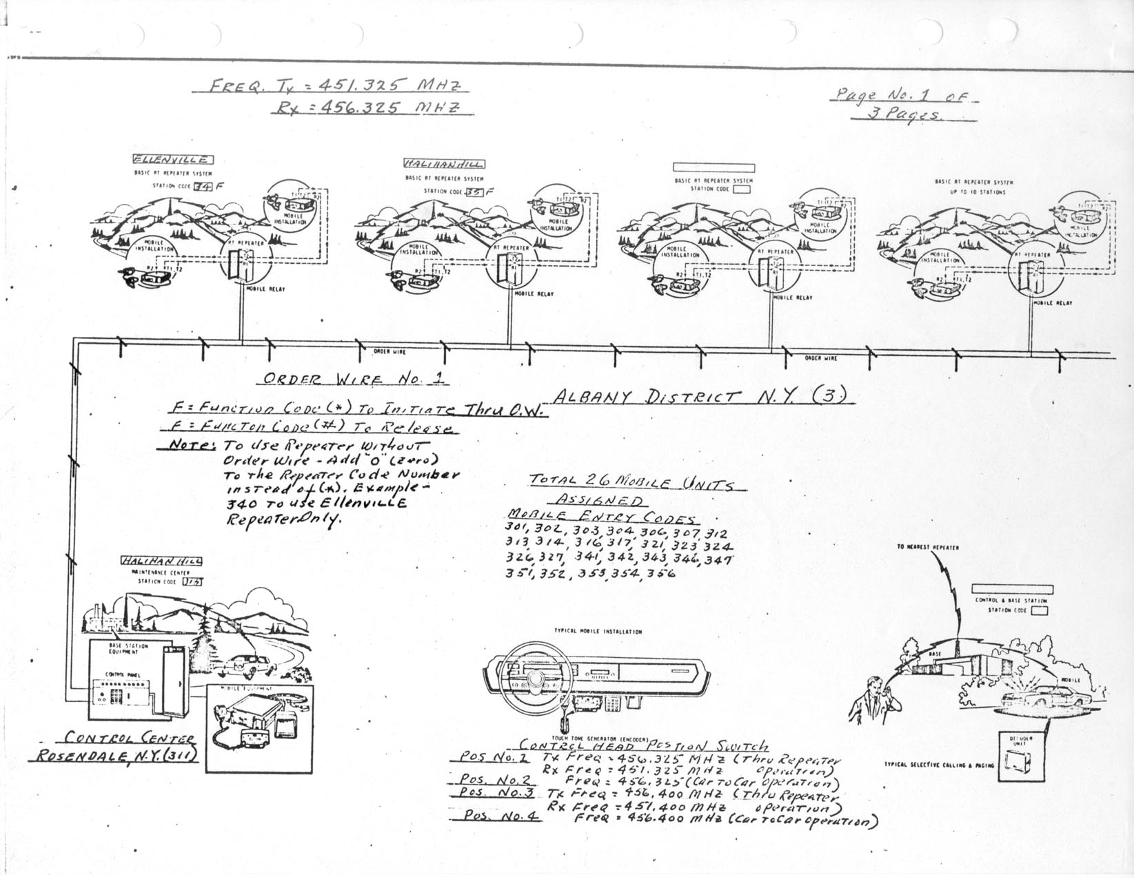
Judging by the Freq assignments, and AT&T heritage, most likely came from the old Long Line sites that used linked repeaters for the field guys. They had quite a bit Motorola products for the two-way infrastuture.
A few freq's that I have been able to come up with from AT&T docs from the day show (for the Albany to NYC service lane):
TX: 456.325
RX: 451.325
TX:456.400
RX:451.400
They also used quite a bit of DTMF for various operations, so there may or may not be some neat DTMF stuff iin there.
A few freq's that I have been able to come up with from AT&T docs from the day show (for the Albany to NYC service lane):
TX: 456.325
RX: 451.325
TX:456.400
RX:451.400
They also used quite a bit of DTMF for various operations, so there may or may not be some neat DTMF stuff iin there.
Lowband radio. The original and non-complicated wide area interoperable communications system

-
Dan562
- Posts: 533
- Joined: Mon Aug 23, 2004 7:30 pm
- What radios do you own?: Kenwood, Yaesu, ICOM, Motorola
Hi PJ,
The last infrastructure SP was done in the spring of 1999 on a MSF5000 station and one of the radio techs came into Schaumburg to make sure the SP modification worked correctly before it went out the door. Funny how things appear to work correctly in the plant but when they get out to the field, they don't work at all. That module was sent back in and the engineer went through it again discovered two gates improperly wired. The final test worked perfectly and AT&T Field Tech tested it several times before he was convinced. I didn't work on that one but I do remember the Touch Tone Decoder interface.
Now that SBC plans to purchase AT&T, I have a feeling this UHF repeater system may go away.
Dan