Playing with a Quantro for the first time, and have a operating voltage question.
The Quantro gets power from one of the MSF5000 PA power supplies mounted above. A seven-conductor cable runs from the power supply to connector J33 on the back plane of the Quantro. The Quantro itself has no internal power supply module.
Of these seven wires, according to the service manual, two are +14VDC and two are ground. With the station off, I measure 0 Ohms between the +14VDC pins on both the power supply and on the corresponding Quantro J33 pins. So, it appears that only +14VDC and ground are really necessary.
Why then is there an extra set of power wires i.e. one extra +14VDC and one extra ground?
Are Quantros 12-14 volt and Quantars 24-28 volt?
I've programmed the Quantro for use as a remote receiver, to provide 2175 Hz idle status tone and RX audio down a wireline. Ideally, I'd like to power the Quantro with a plain old 13.8VDC Astron power supply, and be able to use the MSF5000 PAs and power supplies for something else.
Thanks,
Tom
Quantro operating voltage question
Moderator: Queue Moderator
-
MSS-Dave

- Posts: 770
- Joined: Mon Jun 30, 2003 6:02 pm
- What radios do you own?: XTL5K, NX300, PD782, Spark Gap
Re: Quantro operating voltage question
Can you post the model number? Quantros available in different bands and power levels.....
Re: Quantro operating voltage question
Model number is T5365A
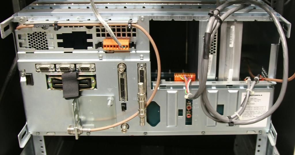
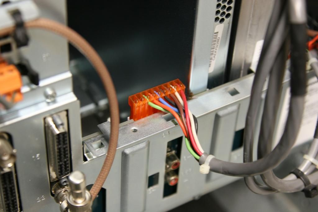
Here is a photo of the Quantro backplane, and a close up of the power connector Q/J33 in question.
According to the manual, J33 pins 1 and 2 are both +14VDC. Pins 3 and 4 are both GND. Pin 5 is OVER VOLTAGE, pin 6 is AC FAIL, and pins 7-9 are open. The cable has 7 total conductors. My question is: why are there two +14VDC wires, are both necessary?


Re: Quantro operating voltage question
And also because those same signals and cable are used on the MSF5000 power supply. Each 14V supply probably has its own fuse. On the MSF5000 one fed the RF Tray and the other was used for auxiliary purposes.
Bob M.
Bob M.
Re: Quantro operating voltage question
kcbooboo wrote:And also because those same signals and cable are used on the MSF5000 power supply. Each 14V supply probably has its own fuse. On the MSF5000 one fed the RF Tray and the other was used for auxiliary purposes.
Bob M.
That's true. I did notice two separate fuses on the supply for these leads. It also makes sense that /\/\ would have used an existing cable. They like to re-use previously engineered parts that way.
So, would it be correct to say that Quantros are 12-14VDC and Quantars are 24-28VDC? Or perhaps low power Quantars are also 12-14VDC?
-
Astro Spectra

- Posts: 668
- Joined: Sat Sep 22, 2001 4:00 pm
Re: Quantro operating voltage question
The two 14V pins on that connector are tied together on the backplane.
The Quantar has a number of different power supply options, with AC and -48VDC inputs along with various standby battery arrangements. The supplies deliver 14V for the low power or 14V and 28V for high power PA options (and +5V).
On the Quantro the 5V is generated by the IPA (low power PA module). So the Quantro chassis can be powered up with just 14VDC if you have the IPA installed. The Quantar needs 14V, 5V, and 28V if high power, so you really need the power supply fitted.
See: http://www.repeater-builder.com/motorol ... index.html
Re: Quantro operating voltage question
@Astro Spectra and others, thanks for all the good info.
This Quantro does have the IPA installed, so it looks like I'll be able to use a simple Astron-type 13.8VDC supply to power it. This will free up the large/heavy MSF power supply for other things.
Tom
This Quantro does have the IPA installed, so it looks like I'll be able to use a simple Astron-type 13.8VDC supply to power it. This will free up the large/heavy MSF power supply for other things.
Tom