While checking a repeater I found what appears to be 7dB of desense. I cannot figure out why, so any help is appreciated. The agency said it had gradually gone "deaf". So on Xmas eve I quickly checked the rx sensitivity with the tx terminated in a good quality dummy load, and measured 0.25uV for 12dB SINAD which seems OK (for a Midland Syntech 70-3400 duplex mobile-wouldn't be my choice for a PSA repeater but there it is). Anyway, I went back today, and re-aligned the Sinclair duplexer with the GD2590 and it looks great, 95dB notches and 2dB pass loss. Not that it was far off in any case. With the tx terminated in a dummy load, I put in a weak signal via an iso-tee into the jumper running from rx to duplexer. On the duplexer ANT port I put another dummy load. I think the TX duplexer port was open, hmmmm.
I found that I needed -60dBm to break squelch in this arrangement. I then connected the tx up to the duplexer, and found I then needed
-53dBm to break squelch. So I seem to have incurred 7db desense simply by having the duplexer in circuit. So either the duplexer is leaking tx signal into the rx, or my test is not valid. I did not use the SINAD method today but relied on the squelch setting.
I did notice that the jumpers are all RG8/U, not sure if that is single or double shielded. Maybe I have jumper to jumper leakage?
TX=155.25, RX=155.685, duplexer =Sinclair Q201G, pl=77Hz in and out.
Thanks.
repeater desense problem
Moderator: Queue Moderator
repeater desense problem
"depending on your point of view, either the changing magnetic flux makes the electric field, or the changing electric flux makes the magnetic field- but you can't have one without the other"
The jumper cables should be double shielded for a split this close. RG214 at a minimum should be fine. On the other hand, since it worked before, you could leave these alone for now.
To test for desense, do not disconnect any cables during the test, just turn the transmitter on and off. You do not want to change the test setup by disconnecting things making the test meaning less.
Do one test with the duplexer antenna port terminated in a dummy load and a second test later on with the duplexer terminated in the antenna / feed line. This will show any antenna / feed line problems that may add to the desense.
While testing, move the cables and see if there is a change in desense. This may point to bad or poor shielded cables and poor connections. In case of the RG8 cables, you may see a noise change. Double shielded cables not only protect against cross talk between the jumpers, they also prevent the antenna radiated signal from entering the system.
Listen on the RX receiver for desense while doing the tests and injecting a weak signal. You should not hear any change in noise level with the TX on or off other perhaps than the initial turn on of the transmitter.
Nand.
My first reaction to a report of "it heard fine for a long time, then starting going deaf" is that the connectors have gone bad and water has leaked into the feedline.
I have found that RG-8 and its associated connectors are very hard to weatherproof, and RG-8 tends to wick water with great efficiency once the water has access to the cable. However, your post wasn't clear as to the spec on the feedline (duplexer to antenna).
I have found that RG-8 and its associated connectors are very hard to weatherproof, and RG-8 tends to wick water with great efficiency once the water has access to the cable. However, your post wasn't clear as to the spec on the feedline (duplexer to antenna).
I agrre that RG-214 would be a better choice, that is on my list of things to do.
I am so far unable to flip the the transmitter on and off because being a mobile radio there is no switch. I suppose if I had the SW I could program a channel with zero output power. That was why I used dummy loads to simulate zero output power, but maybe that is not valid. I did not have the duplexer TX port terminated, I will next time.
The point about the antenna or feedline radiation getting back into the jumpers is a good one.
The feedline is heliax, and the building is all-metal.
Not sure whether it went deaf recently or slowly degraded over a longer period.
I have not checked the VSWR at the TX port of the duplexer, maybe it is not good, so the jumper might radiate?
"depending on your point of view, either the changing magnetic flux makes the electric field, or the changing electric flux makes the magnetic field- but you can't have one without the other"
You left out some of the most important info to help us help you. What kind of feed line is going to the antenna? What type of antenna is being used? How old is the installation? What other radio systems are at the site? Has any new radio transmitters been added recently that could have cause the problem?
In general, what is the site like. By any chance is this a mountain top with a ton of other towers? Did a VHF paging transmitter get added in the recent past to the hill top?
Have you tried an AM radio at the site to see if there is any power line noise? Has there been any high wind about the same time the problem developed? Is it possible that the feedline connectors have water in them and the cold weather has turned the water to ice.
You need to go back to the site with a different view in mind. Look at the overall picture. Take the blinders off and look outside of the radio on the floor. Try to figure out what has changed. Repeater desence is not an easy task to solve. Sometimes it may not even be at the same tower your on.
Give us some more info, so the board can help offer areas to have you go look at.
Jim
Internally generated desense typically shows when you key up the station and try to keep it keyed with a weak signal but the TX signal keeps you from doing so. This results in the repeater cycling on and off continually with a weak input signal. If this is not the case, then there is no serious desense caused by the repeater transmitter.
Here is how you can test this. You already verified that the receiver isn’t deaf. First make sure that the repeater works correctly with a dummy load or better yet, the capable service monitor connected in place of the Heliax to verify that the above problem does not exist. I believe your service monitor is capable of generating a signal while receiving if it has a build in dummy load. You should be able to test the system without disconnecting anything other than the antenna feed line.
As for disabling the TX, since you have no disable switch, can you not turn up the squelch control and keep the TX from keying with a weak input signal. By turning the squelch up and down, you should be able to simulate the turning off and on of the transmitter. Or if the receiver mutes in the above case, perhaps you can wait for the transmitter to time out. Or if that doesn’t apply, pull the keying line.
Once you are convinced that the repeater works fine, you will need to check the antenna system and look perhaps for other sources of desense as mentioned by Jim.
Nand.
You both have raised many good questions, and I will do some more checking. (With blinders off, Jim). Nand, you are correct the monitor has a dummy load and will run duplex. Yes, there is some cycling with a weak signal. No, I don't want to open the radio and cut the COS.
From memory, here is the physical situation..
The site is at 300ft el. with a water tower of 85ft to the tank top. The antenna is at that height, so its tip is at 105ft. Having climbed the tower 3 times this year, I can confirm that the structure is just about rusted out. I removed 3 amateur antennas this summer, leaving only the antenna in question. The whole thing is slated for demolition in about 6 months.
Between the tower legs is a small metal building containing pump controls and this one repeater in question. Nothing else remains in the bldg. The heliax runs down a tower leg and enters the building without a grounding kit. Nor is there a polyphaser. The building has no climate control.
There is a 2ft jumper of RG8/U connecting the heliax to the duplexer. All the other jumpers are RG8/U. There is a Telewave isolator between the transmitter and the duplexer. The isolator has an adapter at its input.
There is a 150W amplifier in the cabinet but it is not connected at this time, I do not know if it ever was.
There is a RV/4 voter also in the cabinet, with one remote receiver in use. Finally there is the 70-3400 Midland mobile masquerading as a repeater, also in the cabinet, with its 110/12V converter.
About a block away is a 50ft pole with several antennas on it one belonging to a pager company at 152.240, another belonging to a commercial ambulance service at 155.22MHz (close).
About two blocks away is another pole with several exposed dipole arrays, I need to find out who and what.
About 1.5 miles away is a site at 600 ft el. with about 20 VHF systems on it, plus cell systems.
Thanks for your comments, if I can get in there again I will post some more results. (They don't like me to shut it down very often)
Bernard.
"depending on your point of view, either the changing magnetic flux makes the electric field, or the changing electric flux makes the magnetic field- but you can't have one without the other"
If you go back up the hill and determine with the service monitor connected to the duplexer antenna port that you have desense from the repeater transmitter itself, you should now replace the RG8 jumpers with RG214.
There is also the possibility that the duplexer has a defective harness. Older Sinclair duplexers weren’t put together like they are today. This doesn’t apply to just Sinclair either.
Because of the small frequency split between RX and TX and the suspected poor front-end selectivity of the radio, I would put a pass cavity between the RX of the duplexer and perhaps another one between the TX and the duplexer as well. The duplexer you are using does not offer any great selectivity at all but they work fine for repeaters with a proper front-end or a wider split with a poor front-end.
It is also possible that no matter what you do, you will have desense because if inadequate internal shielding in the duplex radio.
Nand.

I had a problem with desense on a repeater on a water tower. My receive frequency was 153.770. The problem was caused by a water level sensor in the tank. The sensor was connected to a microprocessor and a UHF radio. I could disconnect the backup battery and ac to micro and noise went away. I could not get any help from water department tech, so we moved the fire dept repeater.
"The world runs on radio."
I agree, the jumpers are next, if the desense test is positive. You mention the duplexer harness, I was wondering about that. It seemed to me that a a bad leak of tx into rx inside of the duplexer would explain the symptoms last time.
The tee of the duplexer is made of exposed-braid cable, hard to say what. It looks very old, my guess is 25 years at least in a damp climate.
The cans do not look like those in the catalog, they have external notch capacitors made from sliding plastic rods in aluminium sleeeves. (Like a WACOM). Perhaps this is a very early design?
I will take a pass cavity or two with me next time.
Thanks.
"depending on your point of view, either the changing magnetic flux makes the electric field, or the changing electric flux makes the magnetic field- but you can't have one without the other"
Sounds like a "Hybrid ring" duplexer. My experience is that because the cabling is all critical lengths, if you change any connection (other than ant) it affects the dupe tuning. So you can't put your isotee in the Rx leg and run the test. Set up as suggested above, and you will get a better "reading" and I also agree, change out all of the 8U to double shielded.
-
ASTROMODAT
- Posts: 1825
- Joined: Tue Nov 05, 2002 12:32 am
It might be easier to replace that mobile duplex radio with a real repeater!
Heck, I just threw away a perfect 75 watt Micor repeater in its 60 inch Compa Station cabinet with DES SECURENET, with factory duplexers, P/S, etc. as their value on eBay is now virtually Zero.
All you would need is to re-crystal the channel elements. By the time you add up your labor over "X" number of hours, re-crystalling a perfect Micor (which are plentiful out there) sounds better than that mobile radio. I've seen MSF-5000 repeaters that have sold virtually new in the box for a few hundred bucks (at the Puyallup Ham Fair).
Larry
-
ASTROMODAT
- Posts: 1825
- Joined: Tue Nov 05, 2002 12:32 am
It might be easier to replace that mobile duplex radio with a real repeater!
Heck, I just threw away a perfect 75 watt Micor repeater in its 60 inch Compa Station cabinet with DES SECURENET, with factory duplexers, P/S, etc. as their value on eBay is now virtually Zero.
All you would need is to re-crystal the channel elements. By the time you add up your labor over "X" number of hours of trying to struggle with the mobile duplex radio serving as a repeater, simply re-crystalling and re-tuning a perfect Micor repeater (which are plentiful out there!) sounds better than that mobile radio. I've seen MSF-5000 repeaters that have sold virtually new in the box for a few hundred bucks (at the Puyallup Ham Fair).
Larry
I have seen several duplexers like the one you may have. I guess at the time that was one way to make a low loss tunable capacitor. Some of these duplexers have the fixed coupling loops on the side of the cans with the adjusting rods clamped to the side with a big hose clamp. Others have the loops on top and the capacitor rods mounted horizontally. The ones I have seen are still operational and in good shape. The were available in their own cabinet with lots of screws.
If you have a hybrid ring as PETNRDX suggested, you will easily recognize it because of the large amount of cables and T connectors hanging all around the duplexer. Hybrid ring duplexers provide very deep notches but are also extremely touchy and can be a source of connector noise. These are really a thing of the past because they cannot be retuned easily in the field without changing all the cables.
If the duplexer is as you describe, it is likely close to 30 years old. You may find that the connector hardware is not up to today’s standards. This also explains the use of RG8 cable that was common in these days.
Again, a test with the service monitor connected to the output of the duplexer should show any desense and noise problems caused by the duplexer and cables that you may not see when tuning the duplexer without power. When doing the test under power, move the cables and lightly tap the connectors. There should not be any change in noise.
I don’t think that replacing a 25 to 30 year old duplexer should be a problem for your customer.
Nand.
With that type of age on the duplexer, you might be facing another problem. The internal connections on the sliding pistons that tune the cavities may be in bad shape. They make connection with finger stock between the fixed tube and the moveable tube. Sometimes just putting some side pressure on the threaded rod will show up this problem or the loose ground to the top plate.
Don't damage the threaded adjustment rod. This is normally made of Formvar and will be hard to find a replacement.
You might be lucky and find that the cavity was silver plated on the inside. With that age, I wouldn't bet on it. If you had the time and they didn't care about the cost, you could rehab all the connections.
The ground connection on the coupling loops could also be poor. It wouldn't take much to mark where the rotation is and pull the coupling loops out. Clean up the mounting area and put the loops back on. They are normally only held in place by 2 small screws. The whole coupling loop and connector mounting plate will just lift out. Just scribe a thin line on the coupling loop round mounting plate and drag it to the cavity top mounting plate. This will make placing the loop back in the same position real easy.
Depending on the type of construction of the cavities, you may also have a poor connection to ground of the internal center adjustable tunning stub. Some companies secured the center tube to the top mounting plate with a single pop rivit. With age and temperature changes, the aluminum pop rivits work loose and it becomes impossible to tune the cavities. If you have the tallent and a drill press, you can do some drill and tap work. Install several stainless screws and secure the center tube better than it was the day it was built.
By all means, change out all the RG-8 cables. Just make sure you match the center pin to center pin length of each cable as you replace them. If you have some small "Heliax" type cable around with connectors, it will be even better than the RG-214.
You might even consider putting some pentrox compound on the threads of the outer shell of the RF connectors. Not only will this give you a better connection, it will prevent the connectors from seizing when you tighten them. Use just a small amount. It goes a long way.
The rusted tank is by no way a good environment. Any small movemant of any part of the tank can cause RF noise problems.
Hope the coax to the antenna is not of the LMR series. That cable has a bad rap for repeater noise issues.
Jim
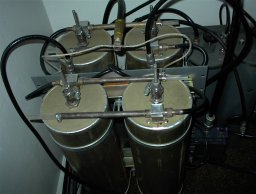
Is this the one?
Found at http://www.qsl.net/kb8mfv/repeater/ using Google.
After increasing the brightness in the picture, you can see that they also added several DB Products 4” pass cavities in the top right corner.
Nand.
Actually, an electrical ground between the loop and the cavity is not needed. As long as it is mechanically stable, all is fine. The loop is only an inductive pickup and could be mounted in a wooden nickel and still work, just not as stable perhaps.Jim202 wrote: The ground connection on the coupling loops could also be poor….
Nand.
Nand, that looks exactly like the cans in the cabinet. All of the harness inside the cabinet is RG8/U (black) except the tee which is exposed braid cable. Outside of the cabinet everything is RG8/U except the feedline which is 7/8 heliax.
Jim, your comments on duplexer rehab are interesting, I may attempt that after they agree that they will buy a new one next year in any case.
Astromodat is right, a new repeater is definitely something to budget for. I think they are getting the message finally.
Thanks to all who replied.
I will post any further findings.
"depending on your point of view, either the changing magnetic flux makes the electric field, or the changing electric flux makes the magnetic field- but you can't have one without the other"
I had a chance today to make some more measurements. As stated the receiver sensitivity is 0.25uV, measured directly into the RX jack, with a dummy load on the TX jack.
So today I disconnected the antenna from the duplexer ANT and replaced it with the monitor in duplex mode. Sensitivity was reduced to 0.9uV. The TX power of 35W was dissipated in the monitor internal load.
Then I removed the isolator from the TX jumper and put in two dummy loads. One to take the TX power, the other to make the duplexer happy.
Sensitivity improved to 0.4uV. Evidently the duplexer must be suspect.
But the cables are also looking suspicious.
Time for new cables.
"depending on your point of view, either the changing magnetic flux makes the electric field, or the changing electric flux makes the magnetic field- but you can't have one without the other"

You aren't talking about very much: 0.25uV to 0.9uV, which sure sounds close to the 7dB or so you mentioned at the beginning. It also doesn't take much bumping or jarring to upset the tuning on those duplexers. In your case, the notch tuning is just a simple variable capacitor.
The cables might be suspect as well, but I hope you don't end up opening a whole new can of worms by replacing them. I'm sure the length is critical, as is the velocity factor of the coax. Either the notch tuning or new jumpers could make the difference for you.
I'd expect the loss in the duplexer to be in the 1-2 dB range, unless it's been set higher due to closer spacing. You aren't far from that right now. It's a good thing when all the numbers agree !
Bob M.
Bob, I am not looking at replacing any internal harness cables of critical length, just the external jumpers. They have two 6 ft jumpers and an isolator in the tx path. One 6ft jumper in the rx path. They don't need to be that long. I would hope the external jumpers are not critical length.
I got some RG214 and have ordered some connectors.
If the sensitivity of the receiver was say 0.5uV measured through the duplexer I would be happy with that, since the Sinclair duplexer is spec'd at 2.2dB loss. But 0.9uV is not so great in my opinion. I suppose we could consider a preamp, suitably protected by bp filters.
The other problem with this system is the antenna, not sure it is the right choice for this situation (600ft hill, steep slope). It is 6dBd gain, so very small vertical pattern angle. Shakespeare 476 I recall. I am looking at a 3 or 4.5dB antenna instead to increase the signal close to the hill.
"depending on your point of view, either the changing magnetic flux makes the electric field, or the changing electric flux makes the magnetic field- but you can't have one without the other"
Well, I made up all new jumpers with RG214, checked them for VSWR, and put them in place of the RG8. No difference. I still get 0.9uV measured at the duplexer ant port. Next up I will try a replacement duplexer, a WACOM 642. If that does not help, I must have a measurement problem.
"depending on your point of view, either the changing magnetic flux makes the electric field, or the changing electric flux makes the magnetic field- but you can't have one without the other"
Just something to check into...
Ther is only .435 Mhz of separation between tx & rx. Many of Sinclair's duplexors do not meet this spec. If you can find an old spec sheet. I'd look into it and see what kind of spec's your duplexor has. 7dB of desense on a "wide band" duplexor does not sound outrageous to me. Newwe Q series Dupl. from Sinclair get into .200 Mhz of separation.
Ther is only .435 Mhz of separation between tx & rx. Many of Sinclair's duplexors do not meet this spec. If you can find an old spec sheet. I'd look into it and see what kind of spec's your duplexor has. 7dB of desense on a "wide band" duplexor does not sound outrageous to me. Newwe Q series Dupl. from Sinclair get into .200 Mhz of separation.