Well, I've searched the archives (found my question, but not the answer), searched the web, searched Usenet news, all to no avail. I cannot find Q552 on my 16-pin assy port Maxtrac.
The photo in the Maxtrac section of Batlabs does not look like my Maxtrac and I'm guessing it was a five-pin model. Will posted written directions for finding Q552 on a 16-pin unit, but his directions don't seem to match my radio.
I've posted a couple of pix of my radio's board here:
http://www.mccurdygroup.com/maxtrac/
I would be most appreciative if somebody could take a look at those pix and help me figure out where that dang transistor is!
Thanks,
Patrick
That elusive Q552 in the 16-pin Maxtrac - how to find it?
Moderator: Queue Moderator

Q552 drives the audio mute FET Q551 on the 5-pin logic boards.
There is no Q552 on the 16-pin logic boards, hence your inability to find it ! They did away with it and drive Q551 directly from U803 pin 6 as a signal called RX MUTE.
If you're looking for a point to use as a COR indicator, I'd suggest U803 pin 6. Unfortunately, this is not an easy spot to get to, but there is a feed-thru on the logic board that you can easily stick a resistor lead into. It's under the shield of the logic board, in the lower left corner (with the front panel connectors facing you), above the 5-terminal regulator that is in the lower left corner. Inside the shielded area you'll find a horizontal row of holes very close to the lower edge of U803. The one at the left, about 1/4 inch from U803, comes from pin 6. This will be logic high when the squelch is opened, for whatever reason.
I'd recommend you connect this through a 4.7k resistor to the base of an NPN transistor and ground the emitter. The open collector will then be pulled to ground when the radio unsquelches. This isolates U803's signal from the outside world. You might need an external pull-up resistor on this new transistor depending on what it's driving.
If you need more, I can scan a section of the manual and send it to you. PM me with an e-mail address. I have done this several times.
Bob M.
Last edited by kcbooboo on Wed Oct 20, 2004 8:38 am, edited 1 time in total.
My first radios were 5-pin logic board Radiuses and MaxTracs which did not have the resistor and transistor COR circuit, so I ended up adding my own without even realizing that the 16-pin boards had that exact same circuitry on them.
I believe that it was the original poster's intent to obtain a COR signal.
Bob M.
I believe that it was the original poster's intent to obtain a COR signal.
Bob M.
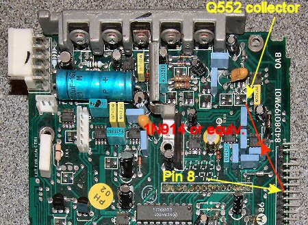
You possibly can use the collector of the PA mute transistor Q509 instead. This collector is resistively (10K) pulled to +13v and to ground when the PA is active. This follows the COR with the exception that the PA is also active when alert tones are heard from the speaker, like when the radio is initially turned on or channels buttons are pressed. The collector is not visible in you photo, but the emitter and base lead are visible.
Bring this pin out through a small diode with the cathode connected to the collector of Q509. The diode anode will be your COR signal that goes to ground when a siganls is received and is open when no signal is present.
Using pin-8 (among others) on the 16 pin accessory connector is a better choice when programmed with the RSS. As n5tbu mentioned, it can be programmed for active high or low and with or without PL needing to be present.

Also see http://www.storm.ca/~nand/990/RICK/rptr.pdf for more info,
and http://www.storm.ca/~nand/990/RICK/cor.jpg for the 5 pin accessory COR connection.
Nand.
Bring this pin out through a small diode with the cathode connected to the collector of Q509. The diode anode will be your COR signal that goes to ground when a siganls is received and is open when no signal is present.
Using pin-8 (among others) on the 16 pin accessory connector is a better choice when programmed with the RSS. As n5tbu mentioned, it can be programmed for active high or low and with or without PL needing to be present.
Also see http://www.storm.ca/~nand/990/RICK/rptr.pdf for more info,
and http://www.storm.ca/~nand/990/RICK/cor.jpg for the 5 pin accessory COR connection.
Nand.
Wow, thanks to everyone for all the valuable information.
If I understand your PDF doc, Nand, I could build the 16-pin ACC port repeater cable and not have to make any internal mods to the radios? Also, would that allow for mic TX on the TX radio if you were standing there at the repeater?
Thanks,
Patrick
If I understand your PDF doc, Nand, I could build the 16-pin ACC port repeater cable and not have to make any internal mods to the radios? Also, would that allow for mic TX on the TX radio if you were standing there at the repeater?
Thanks,
Patrick
I believe that was his intent. You can get all the signals you should need for repeater use from the ACC jack.
The front panel MIC jack is still active regardless of what you have plugged into the ACC jack, unless something there shorts out the MIC input line. I'd suggest that you unplug the front panel mike when you use the radios in repeater service, as not all mikes disable the audio signal when not in use.
If you will be using a MaxTrac as a repeater transmitter, you will need LOTS of cooling air aimed at, and flowing over, the heat sink. Even with all this cooling, the radios still get hot, and may cut off after 30-60 minutes of continuous transmitting. The microprocessor monitors an internal temperature sensor and also keeps track of transmitter ON time, and eventually decides you've talked enough and cuts things back. I don't believe anyone has found a way around this yet, except to use some other radio as a transmitter. But for a not-too-busy repeater, it should work just fine. Eventually you may need to graduate to a base station radio that's capable of running continuously.
Bob M.
Actually, all Motorola microphones that I have seen do isolate the audio line when the PTT is not pressed. So you can leave the mic plugged in if you like. Also, when using the 1.5K resistor shown in series with the capacitor, there won’t be any significant loading on the mic when the radio is used in a repeater.
As Bob said, the radio will get hot and needs a fan when in continuously use. This is also the case if the power is turned down. Maxtracs protect the PA by calculating the TX on and off times together with a temperature measurement of the RF board. Keeping the radio cool will let them run all day. I have not noticed excessive heat with CDM radios when they are turned down in power. This is likely because CDMs use FETs in the PA.
Nand.