Hello All. After my "radio guy" couldnt get it to work, I am now turning to the PROFESSIONALS to get it to work!
I have a UHF Radius mobile and Low band Radius mobile to make a crossband repeater. FOr some reason we cant get it to work - Help!!!
I've followed the directions on the site here, but am confused.....
I realize it's a lot, but can someone please tell me the following:
In the software (which I AM licensed on) what:
UHF Radius what settings should the pins be set to
Low Radius what settings should the pins be set to
I have tried every type from general I/O to phone patch??? HELP!
Thanks!!!!
Thanks in advance to all for the fine help as usual!
_________________
Jay Goldmark, EMT
Ex-Captain, Woodmere Fire Dept.
Fire District Communications Supv.
Woodmere, Long Island, NY
Help w/ home-made crossband repeater
Moderator: Queue Moderator
Help w/ home-made crossband repeater
Jay Goldmark, EMT
Ex-Captain, Woodmere Vol. Fire Dept.
Fire District Communications Supv.
KC2ZHI Amateur Radio Operator
Licensed Master Electrician
Owner, Top Class Electric, LLC.
Woodmere, Long Island, NY
"Enjoy Life, it's not a dress rehearsal !!!"
************************************************************
Ex-Captain, Woodmere Vol. Fire Dept.
Fire District Communications Supv.
KC2ZHI Amateur Radio Operator
Licensed Master Electrician
Owner, Top Class Electric, LLC.
Woodmere, Long Island, NY
"Enjoy Life, it's not a dress rehearsal !!!"
************************************************************

Might also help to give the series of radios, other than 'radius'. I assume the low-band is a 208 or 216, what about the UHF? GM300...M100...M120/130...etc.
Todd
Todd
No trees were harmed in the posting of this message...however an extraordinarily large number of electrons were horribly inconvenienced.
Welcome to the /\/\achine.
Welcome to the /\/\achine.
Yes, the low band is an M208. UHF I have tried everything from a M120, M130, GM300, and Radius M208/216..... I am stumped!
Jay Goldmark, EMT
Ex-Captain, Woodmere Vol. Fire Dept.
Fire District Communications Supv.
KC2ZHI Amateur Radio Operator
Licensed Master Electrician
Owner, Top Class Electric, LLC.
Woodmere, Long Island, NY
"Enjoy Life, it's not a dress rehearsal !!!"
************************************************************
Ex-Captain, Woodmere Vol. Fire Dept.
Fire District Communications Supv.
KC2ZHI Amateur Radio Operator
Licensed Master Electrician
Owner, Top Class Electric, LLC.
Woodmere, Long Island, NY
"Enjoy Life, it's not a dress rehearsal !!!"
************************************************************

From the sounds of this, you're doing it without any kind of interface controller? Just back-to-back radios?
UHF COR -----> Low Band external PTT
Low Band COR -----> UHF external PTT
UHF flat audio out ------> Low band external mic input
Low band flat audio out ------> UHF external mic input
That is all you need for the most basic connections. But you'll need a way to adjust the audio levels which I don't think you get in the Radius software. Nand's handy little interface will take care of that for you. If you were using CDM mobiles, the mic gains are programmable in the software and it's a no-brainer.
"I'll eat you like a plate of bacon and eggs in the morning. "
- Some loser on rr.com
eBay at it's finest:
Me: "What exactly is a 900Mhz UHF CB?"
Them: "A very nice CB at 900Mhz speed!"

- Some loser on rr.com
eBay at it's finest:
Me: "What exactly is a 900Mhz UHF CB?"
Them: "A very nice CB at 900Mhz speed!"
correct., no interface - wire to wire. I did the pinning as per the instructions here on batlabs. What should each radio be set for? General I/O, etc?? I tried everything I could, but still no dice..... sometimes the low band radio will keep intermittently transmitting, but will never hold a key......
Jay Goldmark, EMT
Ex-Captain, Woodmere Vol. Fire Dept.
Fire District Communications Supv.
KC2ZHI Amateur Radio Operator
Licensed Master Electrician
Owner, Top Class Electric, LLC.
Woodmere, Long Island, NY
"Enjoy Life, it's not a dress rehearsal !!!"
************************************************************
Ex-Captain, Woodmere Vol. Fire Dept.
Fire District Communications Supv.
KC2ZHI Amateur Radio Operator
Licensed Master Electrician
Owner, Top Class Electric, LLC.
Woodmere, Long Island, NY
"Enjoy Life, it's not a dress rehearsal !!!"
************************************************************
The RSS settings are best set at General but any selection that gives access to pin 8 will do. The only pin that you are using in this screen is pin 8. It will be the COR pin. This pin 8 should be programmed to function 5 (PL/DPL & CSQ). It also should be set to active LOW. When a signal is received, COR goes low and keys the transmitting radio on its pin 3 (PTT). Do this for both radios if it is to be bi-directional. If you don’t use PL, then program pin 8 for CSQ only (function 7). This can be helpful while testing.
All other pins can or should be set to NULL.
Make sure the internal jumper JU551 on the logic board is in position B. This will give you squelched de-emphasized audio on pin 11. Position A provides flat unmuted and unfiltered audio that sounds terrible.
Do set the timeout timer on both radios to whatever makes sense. Also make sure both radios well connected to the same ground source.
Like nmfire says, CDM radios are really easy to do. All is needed for these is a capacitor to couple the audio.
Nand.
ok sounds good. the low band radio should be receiving CSQ and the UHF is receiving with DPL actually. So please verify: Low band radio should be set to function# 7 while UHF radio should be set to # 5???
thanks for the help!
thanks for the help!
Jay Goldmark, EMT
Ex-Captain, Woodmere Vol. Fire Dept.
Fire District Communications Supv.
KC2ZHI Amateur Radio Operator
Licensed Master Electrician
Owner, Top Class Electric, LLC.
Woodmere, Long Island, NY
"Enjoy Life, it's not a dress rehearsal !!!"
************************************************************
Ex-Captain, Woodmere Vol. Fire Dept.
Fire District Communications Supv.
KC2ZHI Amateur Radio Operator
Licensed Master Electrician
Owner, Top Class Electric, LLC.
Woodmere, Long Island, NY
"Enjoy Life, it's not a dress rehearsal !!!"
************************************************************
Correct.Jay G. wrote:ok sounds good. the low band radio should be receiving CSQ and the UHF is receiving with DPL actually. So please verify: Low band radio should be set to function# 7 while UHF radio should be set to # 5???
thanks for the help!
If you just connect the audio as you say, you will have very loud and distorted audio.
Nand.
UPDATE:
I have the whole thing setup. From Low band to UHF it works. From UHF to low band it doesnt....Settings are all right. I even went so far as to swap the low band radio out, same results. I then swapped the low band for a UHF radio just to see if it was a cable problem, and it works perfectly both ways......
HELP!!!!
Jay Goldmark, EMT
Ex-Captain, Woodmere Vol. Fire Dept.
Fire District Communications Supv.
KC2ZHI Amateur Radio Operator
Licensed Master Electrician
Owner, Top Class Electric, LLC.
Woodmere, Long Island, NY
"Enjoy Life, it's not a dress rehearsal !!!"
************************************************************
Ex-Captain, Woodmere Vol. Fire Dept.
Fire District Communications Supv.
KC2ZHI Amateur Radio Operator
Licensed Master Electrician
Owner, Top Class Electric, LLC.
Woodmere, Long Island, NY
"Enjoy Life, it's not a dress rehearsal !!!"
************************************************************
Ok, from low-band to UHF works...so obviously the pin 8 in the low band is going low on carrier, and keying the UHF radio via pin 3. Have you checked the other way? Does the UHF pin 8 go low when receiving a valid carrier? What radio are you using for the UHF?Jay G. wrote:UPDATE:
I have the whole thing setup. From Low band to UHF it works. From UHF to low band it doesnt....Settings are all right. I even went so far as to swap the low band radio out, same results. I then swapped the low band for a UHF radio just to see if it was a cable problem, and it works perfectly both ways......
HELP!!!!
No trees were harmed in the posting of this message...however an extraordinarily large number of electrons were horribly inconvenienced.
Welcome to the /\/\achine.
Welcome to the /\/\achine.
This diagram does work but probally need a ground line from each radio.
http://www.storm.ca/~nand/990/RICK/rptr.pdf
Pins 7, GROUND on EACH radio need to be tied together.
I use a 2.2uf cap, + to pin2, with a 2.7k to 3k resistor to the second radio's pin 11, and pin 7 on each radio tied together.
[edit]
If you seem to be woried by the ground current thru the radio accessory jack, use a 14 ga ground lead from each radio's power connector mounting screw.
Last edited by Will on Fri Sep 09, 2005 11:11 pm, edited 1 time in total.
Both radios need to be grounded to the same power source, but should not depend on pin 7 to be that ground. The reason is that if at any time the transmitting radio looses main power ground for some reason, it will try to suck all the needed TX current through both radios pin 7 and consequently burn up the tiny trace to this pin 7, if no other ground path is available. Now if both radios are well grounded to start with and there is no chance of either one loosing its proper power ground, then there is no problem tying both pins 7 together. This would particular be the case of both radios were mounted in one solid frame. If a connection between both pins 7 is desirable, place a 1 or 2 amp fuse in there just in case to protect the circuit board traces.Will wrote:This diagram does work but probally need a ground line from each radio.
http://www.storm.ca/~nand/990/RICK/rptr.pdf
Pins 7, GROUND on EACH radio need to be tied together.
I use a 2.2uf cap, + to pin2, with a 2.7k to 3k resistor to the second radio's pin 11, and pin5 on each radio tied together.
The 2.7K resistor that Will suggests is fine in most cases. A variable resistor as used in my diagram gives the ability to provide equal audio or 3 dB boosted audio if desired. Motorola provides this option in most of their repeaters. It gives a bit of “punch” to the retransmitted audio. It is not desirable if signaling is used through the repeater. Also when you have the proper alignment equipment, you can set the repeat audio exactly where it should be.
As for the low band radio not keying up as I assume is the case. Does it the low band radio key up when pin 3 on the accessory connector is grounded? It should. Accessory pin 3 is the same as the front panel PTT pin. It is wired to front panel connector (J8-11) on to the mic connector.
Nand.
Even if it is, it is unlikely that the accessory connector itself is designed for that kind of current. I'd be willing to be the plastic will melt in such a failure where TX current is drawn through that little tiny connector.
"I'll eat you like a plate of bacon and eggs in the morning. "
- Some loser on rr.com
eBay at it's finest:
Me: "What exactly is a 900Mhz UHF CB?"
Them: "A very nice CB at 900Mhz speed!"
- Some loser on rr.com
eBay at it's finest:
Me: "What exactly is a 900Mhz UHF CB?"
Them: "A very nice CB at 900Mhz speed!"
At least we agree that there is the possibility of a high current going through pin 7 when the transmitter radio’s ground gets disconnected for some reason and the this radio now gets keyed up. You investigated this in your lab and found that pin-7 is a solid ground.Will wrote:A fuse is not needed here, the ground at pin 7 on the accessory jack IS a solid ground, not a trace. Just something else (fuse) to go wrong.
We have tested that paticular point here in the lab, even with high power radios.
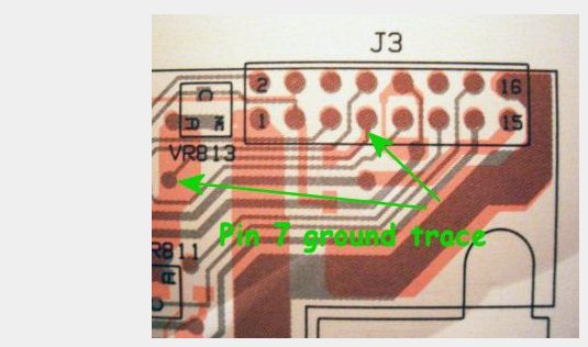
I investigated this in my lab and concluded that pin-7 is grounded by just a tiny circuit board trace in some radios. The picture below from the GM300 manual that I keep in my library tells it all. The tiny trace is visible between the two arrows.
Like nmfire10 says, it is not very likely that the small accessory connector pins can handle the large TX current. If a problem with the power ground weren’t detected in time the connector would seriously overheat. As for “something else to go wrong”, that is what fuses are for. If both radios are properly grounded and bonded together no current should flow between either pin-7. Only if something already went wrong with the grounding will this fuse blow. My drawing purposely does not connect these pins 7 together at all because there is no need for it and may only cause a serious problem if the TX ground does get disconnected.
If you now decide to talk about AC ground, then I would suggest putting a bypass capacitor between the pins 7 on both radios. Observations have shown that this isn’t a problem and therefore isn’t needed either.
I published the diagram for people who like to wire their own or don’t have the money to buy a full featured commercial product like your module. Neither am I posting here for profit. I assume the same applies to you since the price you ask for your model is not very high. I would appreciate it if you would not continually put this 3-component high reliable circuit down for seemingly no other reason that promote your own. I also would really like to see you publish the diagram for your module. Do you have any plans to do so?
Nand.
wavetar wrote:Ok, from low-band to UHF works...so obviously the pin 8 in the low band is going low on carrier, and keying the UHF radio via pin 3. Have you checked the other way? Does the UHF pin 8 go low when receiving a valid carrier? What radio are you using for the UHF?Jay G. wrote:UPDATE:
I have the whole thing setup. From Low band to UHF it works. From UHF to low band it doesnt....Settings are all right. I even went so far as to swap the low band radio out, same results. I then swapped the low band for a UHF radio just to see if it was a cable problem, and it works perfectly both ways......
HELP!!!!
Low band is radius mobile, 16 ch
UHF i have tried GM300 (16ch) and Radius M216
Low band when cables are connected tries to key, but wont hold a tx. keeps "clicking" in and out of TX, but no TX at alll.... From regular mic too when cables hooked up...
and yes, both radios are powered from same source. Thing I dont get is why it works FINE when i swap to anything else then a low band radio.....VHF or UHF GM300,Maxtrac etc...
Is there something in the radio that needs a mod???
BTW: I have a similar setup with a real RICK and it too wont work UHF to low......
HELP!!!!
Jay Goldmark, EMT
Ex-Captain, Woodmere Vol. Fire Dept.
Fire District Communications Supv.
KC2ZHI Amateur Radio Operator
Licensed Master Electrician
Owner, Top Class Electric, LLC.
Woodmere, Long Island, NY
"Enjoy Life, it's not a dress rehearsal !!!"
************************************************************
Ex-Captain, Woodmere Vol. Fire Dept.
Fire District Communications Supv.
KC2ZHI Amateur Radio Operator
Licensed Master Electrician
Owner, Top Class Electric, LLC.
Woodmere, Long Island, NY
"Enjoy Life, it's not a dress rehearsal !!!"
************************************************************
Try to have a very solid connection between both the frames of the two radios involved. It also may be a problem with your power supply since the low band radio draws a lot of current when it goes in TX. See what happens if you lower the power setting for the low band radio.Jay G. wrote: Low band is radius mobile, 16 ch
UHF i have tried GM300 (16ch) and Radius M216
Low band when cables are connected tries to key, but wont hold a tx. keeps "clicking" in and out of TX, but no TX at alll.... From regular mic too when cables hooked up...
and yes, both radios are powered from same source. Thing I dont get is why it works FINE when i swap to anything else then a low band radio.....VHF or UHF GM300,Maxtrac etc...
Is there something in the radio that needs a mod???
BTW: I have a similar setup with a real RICK and it too wont work UHF to low......
HELP!!!!
Nand.
Mr. Nand writes:
""I would appreciate it if you would not continually put this 3-component high reliable circuit down for seemingly no other reason that promote your own. I also would really like to see you publish the diagram for your module. Do you have any plans to do so? "
So, make your diagram more understandable for the Bi directional so called crossband repeaters.
I had thaught of publishing a correction to your diagram, but was waiting for you to do that. IF NOT I am going to do a better diagram/circuit. You have the option here, I am on hold to see what you do.
Mostly for Will?
From another post at another place:
As for the edit in your post, you don’t see the picture the way I do or just don’t want to see it that way. The point is that if for some reason there is no ground on the transmitting radio at the power source, how unlikely that may be, then the only ground left available is the pin-7 ground that you like to tie to the other radio for no good reason since it serves no purpose in a properly power wired configuration. And in a not properly wired configuration is can be the cause of a trace burn when the transmitter keys up. Why take the chance of that when there is no need for it.
Why don’t you just admit that pin-7 is not a solid ground as you claim to have investigated when a photo of the circuit board traces in one of my posts clearly shows that this is not the case, instead of removing the statement from you post in an additional edit? Here is your removed text.
You are not only beating around the bush here, but also trying to change the playing field and in the process screwing up this complete thread. No doubt with my unintentional help.
I created a new pdf file at your request in the PM to me. I also will stop arguing with you in this thread since it doesn't contribute to the original post as nmfire noted.
Will you now post the diagram for your module just out of curiosity? A simple yes or no will do.
http://www.storm.ca/~nand/990/RICK/rptr.pdf
Nand.
From one of the above posts:Will wrote:….
Note here, I do not use the pot in the diagram. I use the capacitor with a 2.2k ohm series resistor, and no adjustment is needed in normal use.
So what is it Will? A 2.2k, 2.7k or 3k resistor?Will wrote:….
I use a 2.2uf cap, + to pin2, with a 2.7k to 3k resistor to the second radio's pin 11, and pin 7 on each radio tied together.
[edit]
If you seem to be woried by the ground current thru the radio accessory jack, use a 14 ga ground lead from each radio's power connector mounting screw.
As for the edit in your post, you don’t see the picture the way I do or just don’t want to see it that way. The point is that if for some reason there is no ground on the transmitting radio at the power source, how unlikely that may be, then the only ground left available is the pin-7 ground that you like to tie to the other radio for no good reason since it serves no purpose in a properly power wired configuration. And in a not properly wired configuration is can be the cause of a trace burn when the transmitter keys up. Why take the chance of that when there is no need for it.
Why don’t you just admit that pin-7 is not a solid ground as you claim to have investigated when a photo of the circuit board traces in one of my posts clearly shows that this is not the case, instead of removing the statement from you post in an additional edit? Here is your removed text.
Will wrote:A fuse is not needed here, the ground at pin 7 on the accessory jack IS a solid ground, not a trace. Just something else (fuse) to go wrong.
We have tested that paticular point here in the lab, even with high power radios.
You are not only beating around the bush here, but also trying to change the playing field and in the process screwing up this complete thread. No doubt with my unintentional help.
I created a new pdf file at your request in the PM to me. I also will stop arguing with you in this thread since it doesn't contribute to the original post as nmfire noted.
Will you now post the diagram for your module just out of curiosity? A simple yes or no will do.
http://www.storm.ca/~nand/990/RICK/rptr.pdf
Nand.
UPDATE:
Corrected power supply issues - Now both radios work fine when tx from the radio's mic itself.
Issues:
Still wont work from UHF to low band. If I touch pin 3 to ground, it keys each radio. Settings are all 100%.
Interesting findings:
Radios dont seem to be working on PL.... The low band signal is being repeated onto UHF, but with no PL....and yes the UHF radio is programmed to tx a PL......
any ideas?
Jay Goldmark, EMT
Ex-Captain, Woodmere Vol. Fire Dept.
Fire District Communications Supv.
KC2ZHI Amateur Radio Operator
Licensed Master Electrician
Owner, Top Class Electric, LLC.
Woodmere, Long Island, NY
"Enjoy Life, it's not a dress rehearsal !!!"
************************************************************
Ex-Captain, Woodmere Vol. Fire Dept.
Fire District Communications Supv.
KC2ZHI Amateur Radio Operator
Licensed Master Electrician
Owner, Top Class Electric, LLC.
Woodmere, Long Island, NY
"Enjoy Life, it's not a dress rehearsal !!!"
************************************************************