Has anyone figured out an easy way to change the channel on a PDR3500 repeater WITHOUT software?
Thanks
Bill
Changing channels on a PDR3500 repeater
Moderator: Queue Moderator
-
Dan562
- Posts: 533
- Joined: Mon Aug 23, 2004 7:30 pm
- What radios do you own?: Kenwood, Yaesu, ICOM, Motorola
The only way I could envision this manual frequency change for multiple RF channels is having the Enhanced Wildcard option, scripting the Wildcard in conjunction with the J17 Systems Connector 50 Pin Telco Connector. Wiring a single wire to each corresponding RF Channel to a Multiple Position Switch and the Common to Ground using J17.
TELCO Connector J17 50-Pins
# 07 Ground
# 17 Aux In 07 (Channel 4)
# 23 Aux In 10 (Ghannel 1)
# 24 Aux In 11 (Ghannel 2)
# 25 Aux In 12 (Ghannel 3)
TELCO Connector J17 50-Pins
# 07 Ground
# 17 Aux In 07 (Channel 4)
# 23 Aux In 10 (Ghannel 1)
# 24 Aux In 11 (Ghannel 2)
# 25 Aux In 12 (Ghannel 3)
What wild card option?Dan562 wrote:The only way I could envision this manual frequency change for multiple RF channels is having the Enhanced Wildcard option, scripting the Wildcard in conjunction with the J17 Systems Connector 50 Pin Telco Connector. Wiring a single wire to each corresponding RF Channel to a Multiple Position Switch and the Common to Ground using J17.
TELCO Connector J17 50-Pins
# 07 Ground
# 17 Aux In 07 (Channel 4)
# 23 Aux In 10 (Ghannel 1)
# 24 Aux In 11 (Ghannel 2)
# 25 Aux In 12 (Ghannel 3)
what 50 pin Telco?
Wrong radio Dan unless it's an antique PDR
The only way is to add the
WIRELINE REMOTE CNTR, PDR Q502
Then get something like the MC2000 ADV TONE DESKSET. That will give you 16 channels depending on how you program it.
If the system is Astro and you want to be able to talk of the wireline you need a DIU
-
Dan562
- Posts: 533
- Joined: Mon Aug 23, 2004 7:30 pm
- What radios do you own?: Kenwood, Yaesu, ICOM, Motorola
Oh, I'm SORRY Bruce1807, the last PDR3500s being shipped from Schaumburg's factory 2 years ago were the Low Power Quantars Repackaged as the PDR3500s. Most of them were being shipped out to the U.S. Federal Government Agencies. Apparently the former Florida SP Engineering Product Group must have modified their radio packages since 2004. Hmmmm .... the original post does not state which PDR3500 version toyradios has and which application the radio is being configured for other than a mult-channel repeater.
If the radio had the regular /\/\ (CTDI) Service Depot Manual, toyradios probably would not need to access BatLabs for advice.
If the radio had the regular /\/\ (CTDI) Service Depot Manual, toyradios probably would not need to access BatLabs for advice.
I purchased one earlier this year and there was no wild card option available.
It is still the low power Quantar
From the Ecat
PDR 3500 is a QUANTAR® product platform based.
Station configuration depends upon model selection.
PDR 3500 is available in the VHF, UHF, and 800MHz bands with power output of 5-30 Watts.
PDR 3500 does not provide ANY local control capabilities.
PDR 3500 is a single mode unit with 16 mode storage capability.
Mode changes are ONLY accomplished via RSS or wireline remote.
CONVENTIONAL REPEATER OR BASE STATION PROVIDES ANALOG AND ASTRO® CONVENTIONAL OPERATION
The PDR 3500 supplies APCO P25 CAI operation capabilities.
The radio can only be configured to pass Analog and ASTRO Digital (ASTRO 9.6kb mode), or Analog alone at one time.
Mode changes are accomplished via Radio Service Software (RSS).
The PDR 3500 when in digital mode can only be configured as transparent.
Encode/decode is not available.
ASTRO remote control operations require a 9.6kbps ASTRO Modem (Q504) and either a 2/4 Wire Wireline (Q502) or 8 Wire Wireline (Q506).
Up to sixteen transmit and receive frequencies, coded squelch (PL or DPL), variable time-out-timer, push-to-talk priority (ptt), repeater drop out delay, and Base Station ID are included as standard. These features ship in a preset condition, but may be altered through the use of Radio Service Software (RSS).
If the station is ordered as a Repeater Operation (Q501), it will support either two antennas, or a single antenna if the Duplexer (Q245) is ordered.
If the station is ordered as a Base Station Operations (H954), it will require an Antenna Relay (Q463) and 2/4 Wire Wireline (Q502) or 8 Wire Wireline (Q506) MUST be ordered.
For VHF and UHF base stations, transmit frequencies can be separated by the full frequency sub-band selected, and receive frequencies can be separated up to 4.0MHz without degradation of specifications.
For repeater operation, transmit, and receive frequencies can be separated by as little as 1MHz without a duplexer.
When the Duplexer (Q245) is ordered then frequency separation between transmit and receive must be as follows
etc.etc.
I don't know anything about PDR3500 radios. However, there is a pretty easy way to change channels in a Quantar:
Assuming this will be wireline controlled from a remote dispatch point, just program some function tones to channel changes in the regular wildcard screen.
The more difficult issue is if the Quantar is to be controlled for channel change locally, such as in a transportable suitcase repeater. We have done this using the Binary Group feature of the wildcard programming, which is available in both the standard and enhanced flavors. Obtain a BCD switch (usually a thumbwheel or pushwheel in configuration) from Mouser; wire it to the appropriate aux I/O lines, and program the channels info to conform to the channel numbers. I've actually only done this using 3-bits (up to 8 channels), but in theory it could be done using 4 bits for 16 channels.
Once you activate the binary channel selection feature, the Quantar will automatically relate channel selection to the binary code made active by your BCD switch; no further programming is required.
Note in any case that channel changing in a repeater is limited by the capability of the associated resonant equipment (i.e., duplexer, multicoupler, combiner).
Changing channels on a PDR3500
Thank you all for the suggestions.
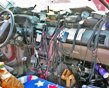
The PDR3500 is a suitcase type repeater.
I'm very interested in the mode RKG mentioned in the post.
Where is the BCD switch installed ?
Do have any wiring diagrams ?
Thanks
Bill
The PDR3500 is a suitcase type repeater.
I'm very interested in the mode RKG mentioned in the post.
Where is the BCD switch installed ?
Do have any wiring diagrams ?
Thanks
Bill
The BCD switch is intalled anywhere that is convenient; it is exterior to the Quantar. In the cases I'm familiar with, it was installed in a faceplate mounted to a rack inside the "suitcase", next to the power switch and mike connector
Wire a good source of chassis ground to the BCD switch common pole. Wire the bit poles as follows:
Bit 0 (LSB) to Quantar AuxIn #1 (Telco Connector Pin 11)
Bit 1 to Quantar AuxIn #2 (Telco Connector Pin 12)
Bit 2 to Quantar AuxIn #3 (Telco Connector Pin 13)
Bit 3 (if used) to Quantar AuxIn #4 (Telco Connector Pin 14)
To avoid ambiguity, fill up any unused channel slots (up to 8 channels with 3 bits and up to 16 channels with 4 bits) with the channel data for your most important channel (usually channel 1).
Set "Active Level" to "Lo".