The General forum is where users can discuss any topic regarding Motorola communications equipment - hardware, software, etc. There are also several focused forums on this board, so please take the time to ensure that your questions doesn't fall into one of those categories before posting here!
Okay, here it is. This repeater will pass secure comms (encrypted twice, but sounds good enough for me). If encryption is not used, then it sounds very good. I used the bottom scematic, because I only needed a standard repeater. Use the top schematic if using a cross band link.
[edit] I got this drawing from firemedic. It was originally designed by ricciticcitembo, but was redrawn in Microsoft Visio by firemedic. Giving credit where credit is due. Sorry guys for leaving you out of the loop.
Here is a drawing I made in Paintbrush to make it easy for someone to plug in the parts exactly where they need to be; no guessing or mapping out your own circuit board. Just about everything can be bought at Radio Shack for very little.
Picture of the "parts" side.
Picture of the "solder" side.
Last edited by RESCUE161 on Tue Jan 24, 2006 9:46 pm, edited 1 time in total.
Mine didn't/doesn't pop either. I don't have a design program, I just used Paintbrush and "zoomed in" to make sure everything looked okay onced I zoomed out. It took a little bit, but it makes it soo much easier.
You could integrate a hang timer into the PTT switching using a 555 timer and some other components. I used to build them over and over for simple Maxtrac repeaters.
Duct tape is like the force, it has a dark side and a light side and it holds the universe together.
"I Reject Your Reality And Substitute My Own!" - Adam Savage
Just to clear things up, (I was thinking while on my run this morning) I did not draw the first image.
[edit] I got this drawing from firemedic. It was originally designed by ricciticcitembo, but was redrawn in Microsoft Visio by firemedic. Giving credit where credit is due. Sorry guys for leaving you out of the loop.
About the hangtime thing, I thought of that, but it hasn't bothered me yet. I figured the less time the transmitter was transmitting, the better.
Last edited by RESCUE161 on Tue Jan 24, 2006 9:48 pm, edited 1 time in total.
I'd say the capacitor on line 15, along with the very slight time delay introduced by the mechanical relay (as opposed to a transistor) takes care of the audio 'pop' sometimes associated with the DC biasing voltage coming onto the speaker outputs. Essentially the same circuit I've made in the past, save for my using a transistor in place of the relay. The 220-ohm resistor between 'speaker low' and ground is interesting...any particular reason that it needs to be in there?
Todd
No trees were harmed in the posting of this message...however an extraordinarily large number of electrons were horribly inconvenienced.
wavetar wrote:The 220-ohm resistor between 'speaker low' and ground is interesting...any particular reason that it needs to be in there?
Todd
I think it just 'mirrors' the relay. The relay is about the same 200 ohms.
If I get the chance this week, I would like to submit a 'later version' that includes the dropout delay ( without using a 555 chip). And the volume control does not affect the TX audio level.
RESCUE161 wrote:Okay, here it is. This repeater will pass secure comms (encrypted twice, but sounds good enough for me). If encryption is not used, then it sounds very good. I used the bottom scematic, because I only needed a standard repeater. Use the top schematic if using a cross band link.
[edit] I got this drawing from firemedic. It was originally designed by ricciticcitembo, but was redrawn in Microsoft Visio by firemedic. Giving credit where credit is due. Sorry guys for leaving you out of the loop.
Here is a drawing I made in Paintbrush to make it easy for someone to plug in the parts exactly where they need to be; no guessing or mapping out your own circuit board. Just about everything can be bought at Radio Shack for very little.
Picture of the "parts" side.
Picture of the "solder" side.
i noticed only one cable output on the box .. what do the plugs look like ??? i assume it is just like the 15 pin connector ... just doubled up ???? the cable dosen't look like it has enough wires in it for 2 connectors
Rule #35
"That which does not kill you,
has made a huge tactical error"
There are two cables coming out, one out of each side. Each one has a 15 pin connector on the end of it. I'll take some pics of the repeater itself when I get home.
Ah, I see (unable to view the pics at work).
The reason that you only see one cable is because the other one was not hooked up at the time I took the pic. Each cable connets to the blue terminals. Hope that clears it up.
A friend of mine is in the process of doing this same idea in a high power version, with clear CW-ID and DES-XL or clear repeater operation tx and rx. BTW, does anyone know the max aperage allowed on the switched B+ (#4 above)?
Wow Looks great. How much for the parts and hold long did it take to build it. How about a "Y" adapter to keep the existing audio active. Would you consider making them and selling them?
You can buy all of the parts for under $10.00 and with the above "Paintbrush" drawing, you just place the parts exactly where they are in the drawing and you're done - VERY easy. The hardest part was mapping out the way I wanted the parts to lay on the board. Now that it's all laid out, the hard work is done.
...does anyone know the max aperage [sic] allowed on the switched B+...
I looked in the Spectra manual. This signal comes from an FET in the control head, so I'd suspect it's good for several hundred mA. It depends on the rating of the transistor, which has a Motorola part number only.
The FET switches the 12 volts that runs the display voltage converter, about 140 ma, and on the Analog Spectra it switches about 250MA for the head 5 volts and the display converter.
It seems that there is the capacity from the FET in the analog Spectras to provide at least 100 MA for the DB15 pin.
The relay draws about 250 MA but that is from the audio output IC.
Hi i build one for my high power spectra’s, (a in-band) it works great, thanks to RESCUE161 and Will, so my question now is can I connect the switch to be used as the horn/lights option, so I can activated the repeater with an MDC call, Sins sum of the pins or being already used?
P.S. I’m thinking of making an outer bored with only the rest of the pins 13,15,6,7, needed for cross-band an jump it to the in-band bored with a switch, so I can have one box with two switches and it will work for in-band or cross-band.
Dear friends
Can you just expain me that can i ues two spectra sets with this unit as repeater. If it is how can I cannect. what is db 15 connecter .can any one help me
Sorry for my poor knolage
thanks
The easiest thing to do is to ignore everything but the "colored" image. Use that to put all of the parts onto a blank circuit board. You can get most to parts, including the circuit board from Radio Shack. The only things that you can't get from Radio Shack are the 2 15-pin plugs and the blue terminal blocks. The terminal blocks aren't really neccessary as you could solder the wires in place.
Reviving this thread from the dead, has anyone sucessfully built the two-way version?
I have been working for a couple hours on designing a circuit board, based off of the original circuit board for the one-way repeater and keep hitting brick walls.
I want to be efficient and not have wired jumpered everywhere and am sure it can be done... but I guess it worse comes to worse I can built two one-way versions and then splice it together at the 15 pin connectors to the spectra, but that's a last resort.
I made a crude diagram, it's a mess to say the least... It has all the components on it and I suspect it's setup properly. It runs pretty symetrical, however my uncertainty makes me less tempted to try it for myself just yet.
Yeah, I took note of that. The closeup shot appears to be different than the one enclosed above... or at least is setup waay differently as the LEDs aren't visible, then again, idk.
The schematic given was pretty hard to follow, even my electronics major friend told me that, but what I have laid out should work. I still haven't had time to solder anything down yet as I go to school full-time and have a part-time job and volunteer other times, and this project is a time-filler for when I'm not busy as hell (if you can believe that)... actually, I do enjoy sleeping as well. This weekend probably won't provide much time.
I'll let ya know how it goes, my design can be improved upon, I just don't have the patience or the mastery of circuit board design to do so. I can try and post pix sometime later.
He has parts on both sides of the board. The LEDs and a few other parts are actually on the solder side.
I wanted all of my parts on one side, so I designed my own layout of the parts. He had more pictures up that showed both sides. I may have saved them, so I'll take a look.
Well, I assembed the whole thing finally, I made sure the circuits all made sense (although the schematic sucked!) and, well... low and behold it doesn't work.
Wired up between two radios, only the on/off LED can be turned off, either LED for TX of the other radio (or RX of one, whatever) are both always on with the radios, one brighter than the other. The Relays aren't clicking, it doesn't do its job at all. I can, transmit the audio from one radio to the other manually by keying it up myself with a hand-microphone.
I can send someone pix of what I have (top and bottom), it's wired up per the instructions and schematics above, it's a :o that it doesn't work, I'm sure it has to be something simple... it was a fluke that I installed all the LEDs backward earlier, but unlike diodes, LEDs aren't as clearly marked, and well resistors and caps don't matter which way they're placed on the board, just as long as the series is proper. I dunno what gives here, I'm rather disgruntled now.
If someone has the time and patience to point out WTF I messed up on, I'd still like it to work. If not, then I'll build two one-way deals side-by-side in project enclosure and run them in opposite directions. PM me your e-mail if interested, especially someone like RESCUE 161 who has some pretty good knowledge of these circuits in particular.
Well disregard, I got it working! I simply forgot to add a jumper to the switch that powers the whole thing. I am excited to test it out in the field as a future cross-band ham repeater, or whatever else I conjure up in the mean time.
I should also comment and make the correction that the diode going between the poles of the K2 relay is backward and should reflect the configuration 'K1' is in.
Other than that, it's a good working schematic, even though it could be cleaned up more.
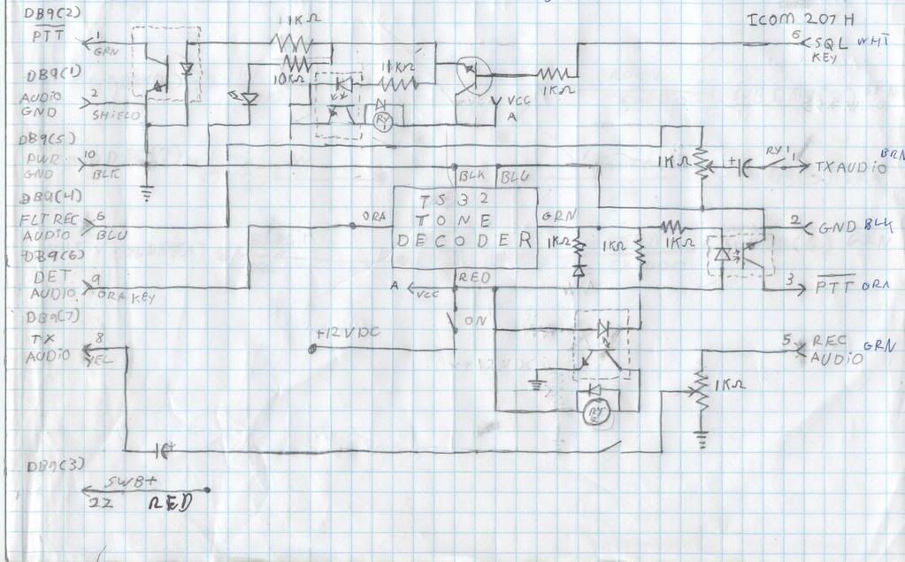
ok here is what I came up with to tie my 900 spectra to my icom 207h radio it could also hook any 2 spectra together. by just hooking the sql lead to one of the speaker leads on the spectra see digram bellow.
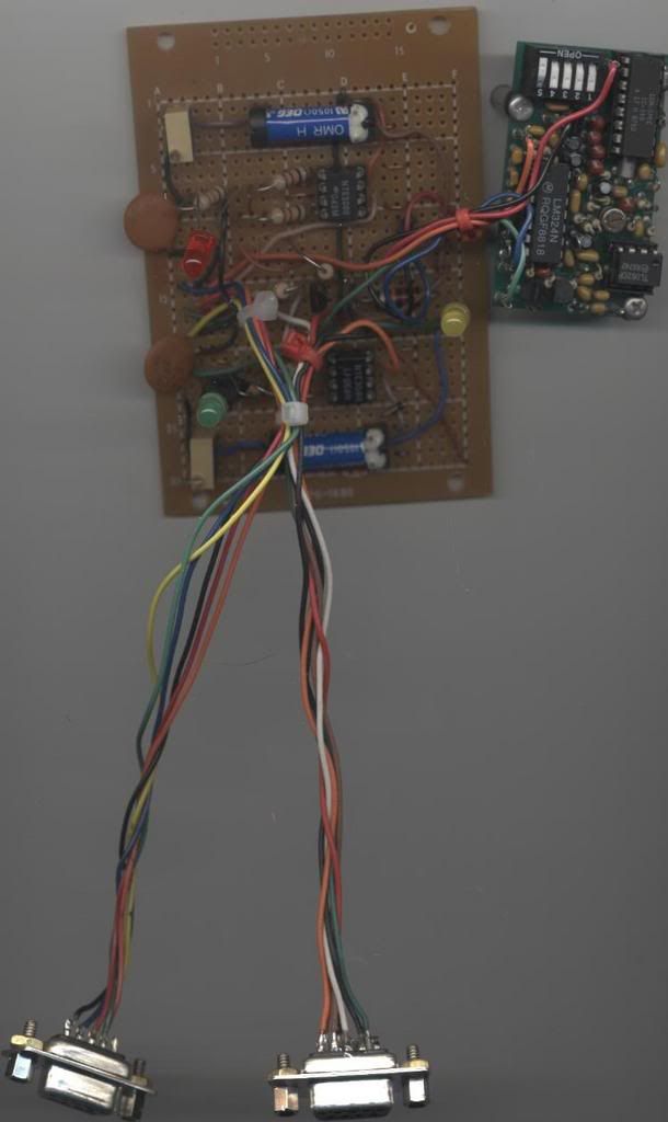
Next you will see my curcuit board
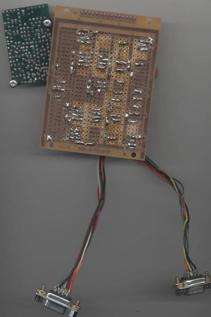
This is the solder side the of the board
The small board is a ts32 tone encoder/decoder that I use with the spectra raw audio to key the icom207h only when the correct tone comes from my portable.
Joel
KE7JOI
1 900 Spectra
1 VHF Spectra
3 900 GTX Portables
1 900 GTX Mobile
I built the "in band" repeater controller some time ago, when I had many astro spectras, but 2009 is no longer the case. I have an astro spectra plus, configured correctly, and an XTL5k that I'm trying to get this to work as the RX radio, but it isn't going well. I took the DB15 connector pinout and matched it to the 26 pin XTL connector, but I'm not getting anything. It should work, but it isn't. I know the XTL doesn't have a COR out the back either, but either the switched B+ isn't the same or something else isn't. I get about 6v off of either speaker lead, so it should be ample to power the unit and run the reed relay.