MTR2000 will not key from tone remote
Moderator: Queue Moderator

MTR2000 will not key from tone remote
I am replacing a MSF5000 C74CXB7106BT with a MTR. There are two consoles of different brands and they both transmitt good on the MSF. When I connect the MTR, one console will not key transmitter. I am using F3 with a function tone of 1350 Hz. The guard tone is -8 db and voice is -8 db at radio. MTR was aligned for these levels. This is a 4 wire control. Auto level is on, wireline squelch is off, tone filter is on. TX line at radio measures 1500 ohms with radio disconnected and consoles connected. I am using half dulpex. Is one console loading the line? Is the MTR less sensitive for function tone or tone frequency tolerance? Console that is not working is adjusted for max tone output and works great with MSF. Does TX wireline alignment in MTR affect function tone? If I align for less tone and voice level will MTR amplify tone more and help problem?
"The world runs on radio."
Re: MTR2000 will not key from tone remote
One very important issue that you always face
with multiple consoles is line loading. The consoles
are generally all set up at the factory to be used
as a single unit on the remote control line. When
you place more units on the control line, these
additional units have to have the loading resistor
removed. This helps to prevent loading the line down.
You may also want to check that the second radio
is set up to respond to the F3 funtion tone. Most
radios will do F1 and F2. When you go above that, y
ou need to make sure the radio will function with
the F3 and F4 function tones.
If the remote control card or board in your radio is
working OK, it should be able to operate with the
idle tone at the -20 db level. If it won't work there,
then you need to find out why. The reason for this
is that the phone company levels will change with
time. If you set your system that low, it will have problems.
Jim
"...Is the MTR less sensitive for function tone or tone frequency tolerance? ..."
_________________________________________________________________
Because your MSF works fine from both consoles and the MTR only works from one, it would appear that the MTR is more fussy in some way. There is certainly a difference between the two station types, but rather than focusing on the difference between the stations - since one of your remotes works OK - the best bet is probably to identify the difference between the working and non-working remote control signals.
A review of the Motorola tone remote control signaling system would probably be a good starting point.
Every tone remote control sequence begins with a burst of high level guard tone (2175 Hz), nominally 115 ms. in length. This burst alerts the circuitry at the station end to be prepared to detect a function tone. The function tone immediately follows the initial high guard burst [no gap] and is nominally 40 ms. in length.
There are a series of function tones from 650 Hz to 2050 Hz in 100 Hz steps. There are several different 'standard' schemes that define how these functions tones are used depending on the station and/or console configuration. Newer equipment allows the tones to be assigned to functions as required.
The functions can be things like frequency selection, repeater setup & knockdown etc. A control sequence can be stand alone or, if voice transmission is to be initiated, transmit audio accompanied by low level guard tone follows the function tone.
There are additional aspects to tone remote control that need to be considered. Not only are the frequencies and durations of the tones defined, the level relationships are specified. The level of the function tone is defined to be 10 dB lower than the high guard tone. The low level guard tone is defined to be 30 dB below the high guard tone. There are also specific relationships between the tone signal levels and the transmit voice levels.
Peak voice level is specified as being the same as the high guard tone level. Average voice level is specified to be 6 dB below high guard [therefore 4 dB above function tone] Average voice level is the level of test tones, alert tones, and the level that should cause your transmitter to deviate at 60% of peak system deviation i.e. +/- 3KHz in standard 5 KHz systems.
Why is all this important? In the days of T1600 consoles and Micor stations, some of these level relationships could vary with no consequences, however, with the introduction of microprocessor based equipment, e.g. CCII, MSF5000, etc, these relationships are fixed - locked in by design and firmware coding. For example on the CCII BIM, there is only a single transmit level control - a master level adjustment only. All the relationships are predetermined.
At the base station [e.g. MSF5000], the station AGC circuitry looks for the high guard tone. When a high guard tone is received, in addition to starting the tone detection and control sequence, the level of that tone locks the AGC and sets the transmit audio gain level for the subsequent transmssion.
As long as all the equipment in the system is Motorola or follows the same level relationships - everything should work fine. If third party consoles are in use - if these have multiple adjustments for various signals - high guard, function tone, transmit level, etc. - it is very important to set the level relationships to match the Motorola system or unreliable operation may result.
In this particular case, you should compare the control sequences of the working and non-working consoles. Your best friend in this task is your DSO - Digital Storage Oscilloscope. With this tool you can capture a complete TRC [Tone Remote Control] sequence. Then, with the trace locked on screen, use the scope's cursors and and measurement readouts to verify the absolute levels, the level relationships, the tone durations, and the tone frequencies.
Once you have pinpointed a difference- your path to a solution will be clear. Here is an example of a DSO capture of a TRC sequence:
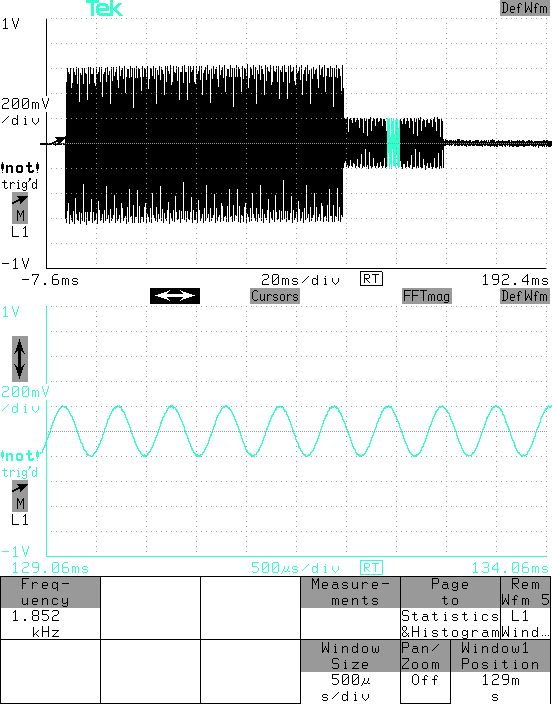
This screen capture shows the use of a dual time base which allows the function tone to be expanded onto a second graticule. The highlighted area shown on the main trace is the expanded area. In this case the scope has measured the function tone frequency as an F2 [1850 Hz] tone.
A DSO like this may be a little overkill to take into the field, but you can get the same results with a handheld instrument like the Fluke Scopemeter. Here we see a screen capture of the same TRC sequence, taken with a Fluke 196. Note that the scope's cursors are showing the function tone duration as 40 ms.
.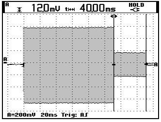
Since the Scopemeter does not have a dual timebase, the determination of the function tone frequency must be done with a second acquisition at a faster sweep speed and with the trigger delay set to cause the capture to take place in the center of the function tone burst
_________________________________________________________________
Because your MSF works fine from both consoles and the MTR only works from one, it would appear that the MTR is more fussy in some way. There is certainly a difference between the two station types, but rather than focusing on the difference between the stations - since one of your remotes works OK - the best bet is probably to identify the difference between the working and non-working remote control signals.
A review of the Motorola tone remote control signaling system would probably be a good starting point.
Every tone remote control sequence begins with a burst of high level guard tone (2175 Hz), nominally 115 ms. in length. This burst alerts the circuitry at the station end to be prepared to detect a function tone. The function tone immediately follows the initial high guard burst [no gap] and is nominally 40 ms. in length.
There are a series of function tones from 650 Hz to 2050 Hz in 100 Hz steps. There are several different 'standard' schemes that define how these functions tones are used depending on the station and/or console configuration. Newer equipment allows the tones to be assigned to functions as required.
The functions can be things like frequency selection, repeater setup & knockdown etc. A control sequence can be stand alone or, if voice transmission is to be initiated, transmit audio accompanied by low level guard tone follows the function tone.
There are additional aspects to tone remote control that need to be considered. Not only are the frequencies and durations of the tones defined, the level relationships are specified. The level of the function tone is defined to be 10 dB lower than the high guard tone. The low level guard tone is defined to be 30 dB below the high guard tone. There are also specific relationships between the tone signal levels and the transmit voice levels.
Peak voice level is specified as being the same as the high guard tone level. Average voice level is specified to be 6 dB below high guard [therefore 4 dB above function tone] Average voice level is the level of test tones, alert tones, and the level that should cause your transmitter to deviate at 60% of peak system deviation i.e. +/- 3KHz in standard 5 KHz systems.
Why is all this important? In the days of T1600 consoles and Micor stations, some of these level relationships could vary with no consequences, however, with the introduction of microprocessor based equipment, e.g. CCII, MSF5000, etc, these relationships are fixed - locked in by design and firmware coding. For example on the CCII BIM, there is only a single transmit level control - a master level adjustment only. All the relationships are predetermined.
At the base station [e.g. MSF5000], the station AGC circuitry looks for the high guard tone. When a high guard tone is received, in addition to starting the tone detection and control sequence, the level of that tone locks the AGC and sets the transmit audio gain level for the subsequent transmssion.
As long as all the equipment in the system is Motorola or follows the same level relationships - everything should work fine. If third party consoles are in use - if these have multiple adjustments for various signals - high guard, function tone, transmit level, etc. - it is very important to set the level relationships to match the Motorola system or unreliable operation may result.
In this particular case, you should compare the control sequences of the working and non-working consoles. Your best friend in this task is your DSO - Digital Storage Oscilloscope. With this tool you can capture a complete TRC [Tone Remote Control] sequence. Then, with the trace locked on screen, use the scope's cursors and and measurement readouts to verify the absolute levels, the level relationships, the tone durations, and the tone frequencies.
Once you have pinpointed a difference- your path to a solution will be clear. Here is an example of a DSO capture of a TRC sequence:
This screen capture shows the use of a dual time base which allows the function tone to be expanded onto a second graticule. The highlighted area shown on the main trace is the expanded area. In this case the scope has measured the function tone frequency as an F2 [1850 Hz] tone.
A DSO like this may be a little overkill to take into the field, but you can get the same results with a handheld instrument like the Fluke Scopemeter. Here we see a screen capture of the same TRC sequence, taken with a Fluke 196. Note that the scope's cursors are showing the function tone duration as 40 ms.
.
Since the Scopemeter does not have a dual timebase, the determination of the function tone frequency must be done with a second acquisition at a faster sweep speed and with the trigger delay set to cause the capture to take place in the center of the function tone burst
-
Dan562
- Posts: 533
- Joined: Mon Aug 23, 2004 7:30 pm
- What radios do you own?: Kenwood, Yaesu, ICOM, Motorola
The MTR2000 Standard 600 OHM Wire Line Module is not designed for the Bridging (High Impedence) applications. Another Infamous /\/\ Engineering Development Mistake between the Canadian and German Duh-velopment Teams. 
But there is an alternative solution that /\/\'s Marketing personnel are unaware of, you can order a FRU CLN1204 (TTN5066) from AAD / NPD. This module will do 2-W or 4-W and can be configured for High Impedence.
But there is an alternative solution that /\/\'s Marketing personnel