
Motorola must have a way to operate a dash-mount control head when it's not physically mounted to the radio. Some kind of extension cable that goes between the command board and the back of the adapter board, or between the adapter board and the actual control head.
Does anyone have info on such a device, or have the actual service cable kit that might have this with it? A photo or detailed description would be helpful.
I'm trying to work on such a control head and need access to the rear of it while it's attempting to operate the radio, but there's no easy way to get to it while it's plugged into the chassis. There has to be a way to do this.
Thanks.
Bob M.
Servicing a Spectra Dash-mount control head
Moderator: Queue Moderator
-
jackhackett

- Posts: 1518
- Joined: Tue Jun 10, 2003 8:52 am
-
jackhackett
- Posts: 1518
- Joined: Tue Jun 10, 2003 8:52 am
Thanks. It looks similar to the one I'm making. I bet Motorola gets a ton of money for it, too.
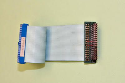
No one makes male plugs that crimp onto the cable, so Motorola made a small circuit board with male pins on it. 40-pin connectors are standard; leave it to Motorola to use a 38-pin connector on the command board.
I found out the hard way that using two IDC connectors on the end of some flat wire flips the two rows around, so while pin 1 is on the same end of the wire, it doesn't connect to the control head's adapter board properly. I think I found a way to "twist" the two rows. I'll post my results after I get it working.
Bob M.
-
jackhackett
- Posts: 1518
- Joined: Tue Jun 10, 2003 8:52 am
What are you using for a board, one of these?
http://www.radioshack.com/product/index ... Id=2102845
Actually, now that I think about it, if you had an extra HLN6285A interface board or two you could make a cable out of those. Take the female connector off of one and solder your ribbon cable in where it was, with a 40 pin IDC on the other end of the cable, or use two, remove the male from one and female form the other and solder a cable between them. Looks like only about half of the 38 pins need to be connected, you'd just have to make sure you match them up right.
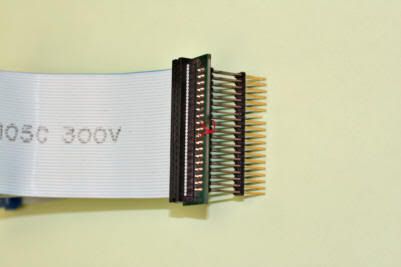
I'm not using a board. 40-pin IDC connector at each end of the cable (that's the easy, obvious part). A 38-pin two-row header, with long studs sticking out of each end, will plug into the command board and let one IDC connector plug into that. The other end will receive the control head interface board.
This is what got me in trouble. When you hold the IDC connectors in your hand, there's no way to get pin 1, on the lower left corner of the command board (which does line up with an arrow on the IDC connector) to orient itself to the same pin on the back of the adapter board. Either you have to rotate the connector so pin 1 is now on the top row of the adapter board, or it's on the other end of the connector.
What I'm going to try to do is twist the pins on the two-row header, so the top row and bottom row are interchanged. A bit of teflon sleeving over every other pin will keep them clear. This will interchange the top and bottom rows only, which is all I think I need to do. I'm sure that a similar swapping is happening in the small circuit board at the end of the Motorola cable, but since I'm not using anything except the header, no soldering is needed but I do have to swap the pins. It all seems possible until I try it. I just hope no pins break during this exercise.
Bob M.
-
jackhackett
- Posts: 1518
- Joined: Tue Jun 10, 2003 8:52 am
-
Lake Effect
- Posts: 311
- Joined: Tue Dec 06, 2005 9:47 am