I have some 403 to 433 Mhz spectras with the A5 head that I want to use for link radio's (overkill I know), Connections I've figured out, however
1 thing left to figure out, is there a way or a modification to keep the radio powered up at all times? so if there is a power bump or outage at the site the radio will come back to life on it's own when the power comes back on. I know with the A4 head it wouldn't be an issue.
With my test configuration I have to hit the power button to bring the radio back to life.
Thanks for any info
Steve
Spectra question
Moderator: Queue Moderator

easy Mod....
You can add a jumper where we previously removed a jumper on A5 Heads in AVL radios. Real easy to do. Instead of removing the jumper wheree noted in the pictures, just add one. Radio will be powered on as long as power is supplied to it.
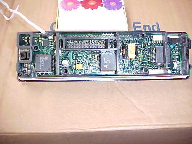
View of head position for modification
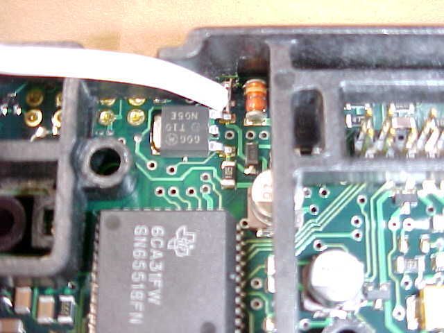
Close up of wire to cut....In your case of jumper to add!
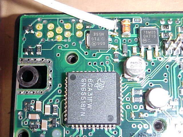
Close up of same jumper to add for constantr power on.

Closeup of jumper after removal.....this is where you need to put one in
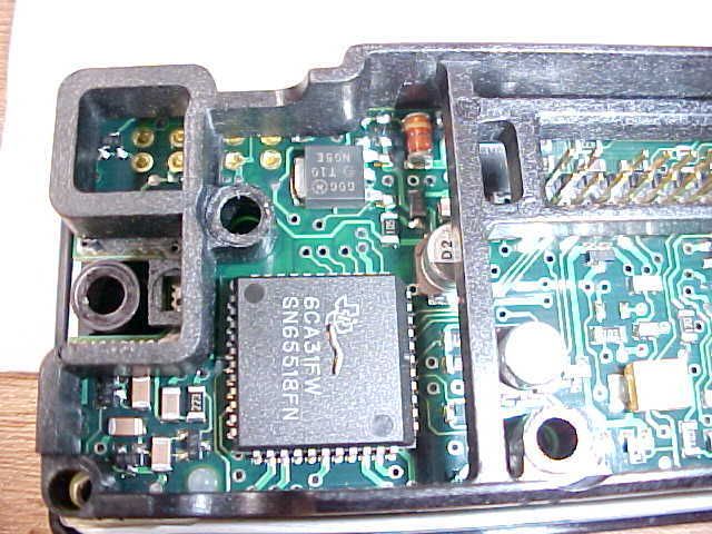
Final Photo of jumper removed.
I know this is backwards from what you asked, but several years ago a bunch of AVL Spectra hit the market and were all constantly powered on. This was the mod to turn the heads back to normal.
GOOD LUCK!
View of head position for modification
Close up of wire to cut....In your case of jumper to add!
Close up of same jumper to add for constantr power on.
Closeup of jumper after removal.....this is where you need to put one in
Final Photo of jumper removed.
I know this is backwards from what you asked, but several years ago a bunch of AVL Spectra hit the market and were all constantly powered on. This was the mod to turn the heads back to normal.
GOOD LUCK!
Scott B.
"Never argue with seven men when you are carrying a six shooter..."
"Never argue with seven men when you are carrying a six shooter..."
Better yet, a jumper on the interface board ( or Command board ) and you do not need the control head!!!!!!
Removing the head and interface board:
On the Command board 38 pin connector:
Jump pin 31 to pin 21 if using the IGN lead
Jump pin 31 to pin 30 without needing the IGN lead
Pin 38 is top left corner with control head and interface board removed.
Pin 20 is top right corner, pin 1 lower left and pin 19 lower right corner.
Discr and filtered audio are there too...
Last edited by Will on Mon Apr 23, 2007 11:42 pm, edited 1 time in total.
what will said!
Or you can just do what will said!!!Will wrote:Better yet, a jumper on the interface board and you do not need the control head!!!!!!
