Hi all
I have a mc micro MAU23EZA3J00AK and i'am having big probs trying to
write to it, using RSS R01.02.01, i have tryed 286\386 25Mnz and 66Mhz pc's without
any luck, i keep getting the error: VERIFY FAIL when trying to write, i have no probs
reading the radio.
Now i have heard that you can edit the small 8pin chip, but i do not know what type it is or the
part number, the numbers on the chip that i have from this radio are:
microchip
8901 JA
PCD8572I
14B02
Is this a eeprom like 24cxx or a serial eprom, if this can be done can any one point me to where i
may find some info on how to do this ??
Thanks in advance
WTD: MC MICRO parts info
Moderator: Queue Moderator
Re: WTD: MC MICRO parts info
Hi
PCD 8572 is a Phillips part number, is a 24C00 serial Eprom, both can be replaced with one 24C04.
Sometimes the write protection is enabled, just check Pin 7 on both eproms, it must be grounded, check for a cutted 0 Ohm resistor that connected to Pin 7, repair them, and thats its.
Jan
PCD 8572 is a Phillips part number, is a 24C00 serial Eprom, both can be replaced with one 24C04.
Sometimes the write protection is enabled, just check Pin 7 on both eproms, it must be grounded, check for a cutted 0 Ohm resistor that connected to Pin 7, repair them, and thats its.
Jan
Re: WTD: MC MICRO parts info
Hijimlovell wrote:Hi
PCD 8572 is a Phillips part number, is a 24C00 serial Eprom, both can be replaced with one 24C04.
Sometimes the write protection is enabled, just check Pin 7 on both eproms, it must be grounded, check for a cutted 0 Ohm resistor that connected to Pin 7, repair them, and thats its.
Jan
Ok found two "0" ohm links (JU705 and JU706) that were cut, one side of each are connected to pin 7 on each ic, other side is ground (-), joined them back, but still getting ERROR: VERIFY FAIL.
This radio only has 1 ic fitted (pdc8572)
Can you think of any thing else that might be the prob ??
Thanks again
-
motoroladealeruk
- New User
- Posts: 20
- Joined: Thu Jun 12, 2008 2:31 am
- What radios do you own?: GP320 GP340 GP360 GP380 GP680
Re: WTD: MC MICRO parts info
I have here some information of the connector pin-outs and also what each zero ohm resistor is for (used as jumpers)
==========
CONNECTORS:
==========
J5(DB9)
PIN.....DESCRIPTION
1........PTT INPUT
2........AUDIO GND INPUT
3........GND (Hang up optional with jumper)
4........SPEAKER Hi Pot OUTPUT
5........SPEAKER Lo Pot OUTPUT
6........MICROPHONE Hi Pot INPUT
7........BUFFERED RX AUDIO OUTPUT
8........EXTERNAL ALERT OUTPUT
9........EMERGENCY SWITCH INPUT
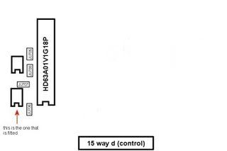
The pinout of the DB15 Control Head connector is as follows:
J4(DB15)
PIN.....DESCRIPTION
1........CALL(Spare)
2........PTT
3........Vol Cont HI
4........Audio GND
5........Spkr Hi
6........B+
7........HUG/PGM
8........F1/F2(DATA2)
9........Tx Busy (RESET)
10.......Mic Hi
11.......Vol Cont Wiper
12.......Spkr Lo
13.......SW B+
14.......GND
15.......CSQ/UNSQ(DATA1)
-----------------------------------------
=======
JUMPERS
=======
STANDARD JUMPERS:
-------------------------------------------------------------------------------------
Jumper....Description..........State...........................GLN6626A.....GLN6628A
-------------------------------------------------------------------------------------
JU551......RX Audio............Flat Response.....................Out...........Out
JU552.............................De-Emphasis Response..........In..............In
JU601......TX Audio............Flat Response.....................Out...........Out
JU602.............................Pre-Emphasis Response.........In..............In
JU701......Control Head I/O..Serial Mode........................In..............In
JU702..................................................................Out............Out
JU703..................................................................In...............In
JU704..................................................................Out............Out
JU705......U702 IC Type.......?...................................Out............Out
JU706......U703 IC Type.......?...................................Out............Out
JU707......OSC Pull..............Disable...........................In..............Out
JU710......Emergency...........Disable...........................Out............Out
JU801......Decode Filter........Select 5 (GLN6628A)...........Out............In
JU802...............................PL (GLN6626A).................In..............Out
JU805......Sidetone..............Enable............................DC.............In
-------------------------------------------------------------------------------------
-------------------------------------------------------------------------------------
OPTION JUMPERS:
-------------------------------------------------------------------------------------
Option.....Jumper......Signaling Type......................GLN6626A........GLN6628A...
MAB470...JU710........Emergency + ext switch.............DC..............Out
MAB688..............................................................?................?..............
MAB873..............................................................?................?..............
MAB459...JU805........Sidetone disabled......................DC..............Out
MAB875...JU803........Fixed Level Alert Tones..............Out..............Out
............JU804...................................................In................In
MAB884...JU551........Flat Audio Response...................In................In
............JU552...................................................Out..............Out
............JU601...................................................In................In
............JU602...................................................Out..............Out
MAB891...JU701........Parallel mode control head...........Out..............Out
............JU702...................................................In................In
............JU703...................................................Out..............Out
............JU704...................................................In................In
MAB888...JU706...................................................In................ --
-------------------------------------------------------------------------------------
Hope this helps! Sorry about the chart layout, after tinkering and tinkering it was the best i could get it to display like in the forum. Probably varies from screen to screen but the columns are nearly lined up well on mine so hope you can view it like i am!!!
==========
CONNECTORS:
==========
J5(DB9)
PIN.....DESCRIPTION
1........PTT INPUT
2........AUDIO GND INPUT
3........GND (Hang up optional with jumper)
4........SPEAKER Hi Pot OUTPUT
5........SPEAKER Lo Pot OUTPUT
6........MICROPHONE Hi Pot INPUT
7........BUFFERED RX AUDIO OUTPUT
8........EXTERNAL ALERT OUTPUT
9........EMERGENCY SWITCH INPUT
The pinout of the DB15 Control Head connector is as follows:
J4(DB15)
PIN.....DESCRIPTION
1........CALL(Spare)
2........PTT
3........Vol Cont HI
4........Audio GND
5........Spkr Hi
6........B+
7........HUG/PGM
8........F1/F2(DATA2)
9........Tx Busy (RESET)
10.......Mic Hi
11.......Vol Cont Wiper
12.......Spkr Lo
13.......SW B+
14.......GND
15.......CSQ/UNSQ(DATA1)
-----------------------------------------
=======
JUMPERS
=======
STANDARD JUMPERS:
-------------------------------------------------------------------------------------
Jumper....Description..........State...........................GLN6626A.....GLN6628A
-------------------------------------------------------------------------------------
JU551......RX Audio............Flat Response.....................Out...........Out
JU552.............................De-Emphasis Response..........In..............In
JU601......TX Audio............Flat Response.....................Out...........Out
JU602.............................Pre-Emphasis Response.........In..............In
JU701......Control Head I/O..Serial Mode........................In..............In
JU702..................................................................Out............Out
JU703..................................................................In...............In
JU704..................................................................Out............Out
JU705......U702 IC Type.......?...................................Out............Out
JU706......U703 IC Type.......?...................................Out............Out
JU707......OSC Pull..............Disable...........................In..............Out
JU710......Emergency...........Disable...........................Out............Out
JU801......Decode Filter........Select 5 (GLN6628A)...........Out............In
JU802...............................PL (GLN6626A).................In..............Out
JU805......Sidetone..............Enable............................DC.............In
-------------------------------------------------------------------------------------
-------------------------------------------------------------------------------------
OPTION JUMPERS:
-------------------------------------------------------------------------------------
Option.....Jumper......Signaling Type......................GLN6626A........GLN6628A...
MAB470...JU710........Emergency + ext switch.............DC..............Out
MAB688..............................................................?................?..............
MAB873..............................................................?................?..............
MAB459...JU805........Sidetone disabled......................DC..............Out
MAB875...JU803........Fixed Level Alert Tones..............Out..............Out
............JU804...................................................In................In
MAB884...JU551........Flat Audio Response...................In................In
............JU552...................................................Out..............Out
............JU601...................................................In................In
............JU602...................................................Out..............Out
MAB891...JU701........Parallel mode control head...........Out..............Out
............JU702...................................................In................In
............JU703...................................................Out..............Out
............JU704...................................................In................In
MAB888...JU706...................................................In................ --
-------------------------------------------------------------------------------------
Hope this helps! Sorry about the chart layout, after tinkering and tinkering it was the best i could get it to display like in the forum. Probably varies from screen to screen but the columns are nearly lined up well on mine so hope you can view it like i am!!!
UR AVERAGE LIFE EXPECTANCY RAPIDLY DEGRADES THE MINUTE U BECOME A SERVICE ENGINEER
Dropping a radio into a toilet filled with "used" water is NOT "slight water damage"
PLEASE don't send it in for repair! (Or at least drain it first)
Dropping a radio into a toilet filled with "used" water is NOT "slight water damage"
PLEASE don't send it in for repair! (Or at least drain it first)
Re: WTD: MC MICRO parts info
We have had EEPROM failures in the R100 (MC Micro based) and the EEPROM was bad. Replaced EEPROM with new one that we had to preprogram.
Even the replacements from Motorola were bad, old stock. Now NLA from /\/\.
Seems the EEPROMs lose their memory with age.....
Even the replacements from Motorola were bad, old stock. Now NLA from /\/\.
Seems the EEPROMs lose their memory with age.....