Hello All,
I am searching for any and all info on the TTE1752A power amp...
There is next to no info available on-line it seems.
All I do know at this stage is that it produces ~150W with ~4W input, beyond that - nothing!
The main information I do require is the safe min-max input power for this unit.
Would anyone know if this unit belongs to the micor range?
Many thanks in advance for any assistance, cheers.
(Micor?) TTE1752A Specs/info wanted
Moderator: Queue Moderator
-
Dan562
- Posts: 533
- Joined: Mon Aug 23, 2004 7:30 pm
- What radios do you own?: Kenwood, Yaesu, ICOM, Motorola
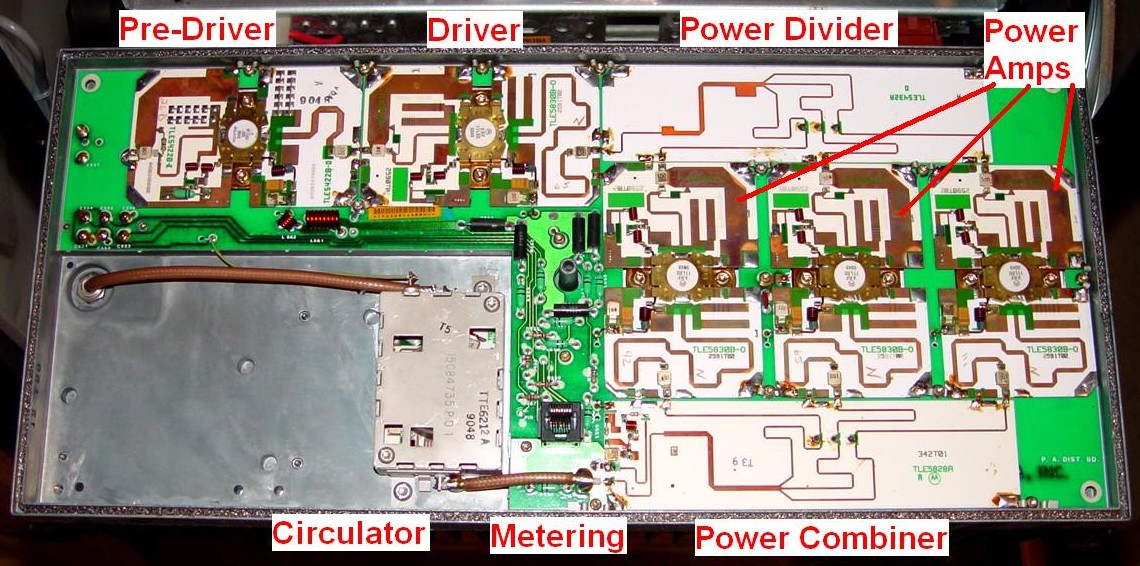
Your TTE1752A appears to be a MSF5000 2 Range RF Power Amplifier with the 3.5~4 Watt RF Drive Level and 150 Watt RF Output. I'm providing a link to the Repeater Builders website so you can verify the internal RF component layout of your Power Amplifier:
http://www.repeater-builder.com/motorol ... inside.jpg
http://www.repeater-builder.com/motorol ... inside.jpg
Dan,Dan562 wrote:Your TTE1752A appears to be a MSF5000 2 Range RF Power Amplifier with the 3.5~4 Watt RF Drive Level and 150 Watt RF Output. I'm providing a link to the Repeater Builders website so you can verify the internal RF component layout of your Power Amplifier:
http://www.repeater-builder.com/motorol ... inside.jpg
After viewing that pic I am 99% sure you are right on the money. I will need to open it up again to confirm but that is indeed identical to the best of my recollection.
I should mention that eventually I would like to use this amp as a linear amplifier in the traditional sense of the word, using just a single transceiver. Obviously I will need some form of switching to allow the transceiver to RX from the antenna. Anyone have ideas on a easy solution to this? I am not familiar with Motorola equipment, apart from some of their common commerical rigs.
I will try some further searches on 'MSF5000', but if you are aware of any other sources of info on the amp I would be eternally greatful. As youre probably aware there is not a lot of information on-line, thanks so much for your help Dan, most appreciated!
-
Dan562
- Posts: 533
- Joined: Mon Aug 23, 2004 7:30 pm
- What radios do you own?: Kenwood, Yaesu, ICOM, Motorola
Here's an Update, if you have provided the correct /\/\ Kit # TTE1742A, you've remove the RF Power Amplifier's metal shield and count six (6) RF Transistors across the amplifier stage in patallel, then you have a High Power RF Class "C" FM Amplifier with the RF Drive requirenemts of 100 Watts and a RF Output of 225 Watts! The required A+ Power Supply Voltage is +24V DC. This RF Amplifier was used in the MSF5000 1/4 KW and the Quantro 1/4 KW Base Stations. The frequency coverage is from 435 - 475 MHz. Reference UHF Service Manual # 68-81092E80.
To my knowledge 99% of /\/\ RF Power Amplifiers are FM / FDMA (Digital) Class "C" amplifiers with the exception of the iDEN 800, 900 & 1500 MHz TDMA Digital and the MICOM 2 - 30 MHz AM / SSB are Class "AB" Linear operation amplifiers.
To my knowledge 99% of /\/\ RF Power Amplifiers are FM / FDMA (Digital) Class "C" amplifiers with the exception of the iDEN 800, 900 & 1500 MHz TDMA Digital and the MICOM 2 - 30 MHz AM / SSB are Class "AB" Linear operation amplifiers.
Hi Again Dan,Dan562 wrote:Here's an Update, if you have provided the correct /\/\ Kit # TTE1742A, you've remove the RF Power Amplifier's metal shield and count six (6) RF Transistors across the amplifier stage in patallel, then you have a High Power RF Class "C" FM Amplifier with the RF Drive requirenemts of 100 Watts and a RF Output of 225 Watts! The required A+ Power Supply Voltage is +24V DC. This RF Amplifier was used in the MSF5000 1/4 KW and the Quantro 1/4 KW Base Stations. The frequency coverage is from 435 - 475 MHz. Reference UHF Service Manual # 68-81092E80.
To my knowledge 99% of /\/\ RF Power Amplifiers are FM / FDMA (Digital) Class "C" amplifiers with the exception of the iDEN 800, 900 & 1500 MHz TDMA Digital and the MICOM 2 - 30 MHz AM / SSB are Class "AB" Linear operation amplifiers.
They say a picture is worth a 1000 words, so:
http://img484.imageshack.us/my.php?image=pa1modzp8.jpg
http://img100.imageshack.us/my.php?image=pa2modhi7.jpg
If we are talking about the same beastie then wow... 225W!
Might explain why my poor little 30A power supply's Amp meter was pinned to the far right...
I gave the amp a very brief input of 5W, the minimum amount I could feed it for the moment. Alas it appears my SWR/Power meter needs calibration so I cannot determine what kind of power it was producing, suffice to say it was pulling at least 30A from the power supply, so that is some indication.
Anyway, the pics should end the conjecture as to it's identity and spec.
Thanks again,
Wayne
[/img]
Ah, just noted the '1742A', whereas mine is a 1752A...
-
George
- Posts: 266
- Joined: Wed Apr 16, 2003 11:14 am
- What radios do you own?: X9000, HT1550XLS, MTS2000, etc
msf power amp
You have a 100 watt range 2 power amp.
It's equipped with a single circulator.
George
It's equipped with a single circulator.
George
-
Dan562
- Posts: 533
- Joined: Mon Aug 23, 2004 7:30 pm
- What radios do you own?: Kenwood, Yaesu, ICOM, Motorola
TTE1742A-SP01 MSF5000 110 Watt RF Class C (NOT a Linear) Amp
Since George has verified your MSF5000 RF Amplifier with the internal Single Circulator as being what you have, there’s still something different about the Base Station RF amplifier. You should note there’s the SP01 stamped on the assembly. I’m not sure what the SP01 (Specialty Products) or special modification option does or was intended to do but it’s incorporated into this particular power amplifier. The original customer paid extra money $$$$$$ to have this option when the station was first sold.
Since you haven’t specified what application you’ve intend to use this RF Power Amplifier in, repeater, mobile or portable, then all I can provide are recommended components and circuit reference sources.
http://www.surplussales.com/Relays/rfco ... x_uhf.html
1 - DPDT 12V DC T/R RF Relay (KC) CX-800M UHF (SO-239)
RF Sensing T/R Circuitry can be found in the ARRL’s Yearly Handbook under the FM section for solid-state RF amplifiers. The handbook should provide enough circuit information how to construct the sensing circuit and wiring the DPDT T/R relay into the circuit.
1 – SPST Mini-Toggle Switch (To switch Amp In or Out in the RF Sensing circuit)
http://www.surplussales.com/Feedthrus/FTholeMnt3.html
2 - (FRI) FT2425-101 100 pF 200v Feed thru Capacitors
http://www.surplussales.com/FerMisc/FerMisc-4.html
2 – (ICH) CHOKE112 95uHy Ferrite
1 – Mini-Box and mechanical hardware for mounting the DPDT antenna relay and RF sensing relay circuit board.
2 – N Type either Crimp or Reducer Connectors for RG-400/U or RG-141/U RF Cable
6 – PL259 or Crimp Connectors
6 – UG-175 Reducers for the RF cable
8 ~ 12 Feet of RG-400/U Double Shielded Stranded Center Conductor Coaxial Cable
or
RG-141/U Double Shielded Solid Center Conductor Coaxial Cable
5 ~ 8 Feet of # 16 or 18 AWG Red and Black Teflon Stranded Hook Up Wire
6 – Metal Standoff Spacers with hardware for mounting PC board and the DPDT Coaxial Relay.
Use Heat Shrink Tubing over all new components and in-line wiring soldered connections to prevent shorting after metal shield is fastened back down.
Take special care when selecting a location to drill and mount the Feed thru filter capacitors so there will not be any damage to the RF transistor ceramic PC hybrids or direct shorts to the Power Amplifier’s components.
You should consider how you would mount this amplifier because of the heat dissipation its produces in normal operation. It’s normally mounted with the fins vertical and 2 or 3 mini-fans blowing across the metal fins to maintain a relative cooling effect. If you can not mount the amplifier in the standard configuration then mount it so the metal fins face upwards allowing the heat to rise away from the amplifier. I would also consider leaving 1 & 2” between the metal shield cover and the mounting surface for air circulation.
If you have a better source than Surplus Sales of Nebraska by all means use the less expensive supply company of your choice.