Sorry for such a basic question, but I'm encountering an XTVA for the first time and I don't have the install manual.
I see there are three wires to power the XTVA: A fused YELLOW wire, a fused RED wire, and a BLACK ground wire.
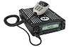
I see in the pinout shown here on the board that the RED wire is "A+" and the YELLOW wire is "Ignition".
Does this mean RED to +12V battery (non-switched), YELLOW to +12V switched (on and off via ignition)?? And, just out of curiosity, what would "A+" stand for, except for a mark I got even close to seeing in school?
Thanks,
Peter
K1PGV
XTVA: A Yellow Wire, a Red Wire... BOTH to +12V?
Moderator: Queue Moderator
-
Tom in D.C.
- Posts: 3859
- Joined: Tue Sep 04, 2001 4:00 pm
- What radios do you own?: Progreso soup can with CRT
Re: XTVA: A Yellow Wire, a Red Wire... BOTH to +12V?
Peter,
You figured it out exactly right. On the bench, and in simple setups, we usually
just tie the red wire and the ignition sense wire together. XTVAs and similar adapters
don't pull much current, usually, so what I've done more often than not is to tie
the two wires together in the car and run them to a convenient auxiliary voltage
source/point which might or might not be ignition-controlled, depending on the
way the circuit is wired. On a circuit where the B+ draws a lot of current there's
and obvious need for B+ direct wiring with ignition-sense control -- or not, depending
on what you personally like.
Regards,
Tom in D.C.
In 1920, the U.S. Post Office Department ruled
that children may not be sent by parcel post.
In 1920, the U.S. Post Office Department ruled
that children may not be sent by parcel post.
Re: XTVA: A Yellow Wire, a Red Wire... BOTH to +12V?
Thanks Tom. I appreciate the assistance.
I just wanted to be avoid toasting my nice new XTVA.
Peter
K1PGV
I just wanted to be avoid toasting my nice new XTVA.
Peter
K1PGV
-
Twisted_Pear

- Batboard $upporter
- Posts: 510
- Joined: Thu Sep 06, 2001 4:00 pm
Re: XTVA: A Yellow Wire, a Red Wire... BOTH to +12V?
If it's an XTS3000 or simular XTVA and you wire both leads to ignition you will get a back voltage from the portable battery when you turn your ignition off. Don't know if there has been a fix for this or not. The XTVA is designed to continue to charge the portable battery after the ignition is turned off for about 30 min or until the battery is charged. We connect the yellow to ignition and red to battery and have no problems.
Re: XTVA: A Yellow Wire, a Red Wire... BOTH to +12V?
I am in Afghanistan and trying to make a quick cross band link using one VHF and one UHF XTS5000 radio with a XTVA vehicular mount. I have a simple TransPeater interface which works great as a VOX unit between the two radios to give me the link I need, however, the battery needs to be charged and from all I can gather, leaving the radios in a charger will not keep them charged, one left on. I need a solution to keep the batteries charged, if anyone knows an easy way to do so. I have looked into the purchase of a battery eliminator but it takes many weeks to order anything here through the military so I'm looking fo a quick fix. I thought using a XTVA vehicular mount for the radio would do it, but when trying to get the audio from the 25 pin DB25 connector it appears it doesn't come out there. I could wire to the speaker output but don't have the connector needed or any kind of pin to insert there. Also, when trying to get the radio to PTT through the PTT pin on the DB25 it does not key up into transmit when taking that pin to ground as I was hoping it would. Does anyone have any information on that XTVA DB25 interface beyond when I found in this thread? What would produce a PTT through those pins and what is expected on the "Visor MIC" pin for levels etc?
I had wired these two radios together though speaker mic cords and it worked great, but without an ability to keep the radios charged, they won't work that way. Anyone know of a work around to keep the batteries charged with a charger, modified to keep the radio charged? If there was such a mod or work around I'd forget the use of the XTVA cradles.
Regards,
Chris KL7FB
Wadsworth, Ohio.
Re: XTVA: A Yellow Wire, a Red Wire... BOTH to +12V?
I have given up on using the XTVA MIC or DB25 input connectors as there are DC voltages present on the MIC inputs which prevented me from being able to use a TranPeater with it. Instead I am looking for info on how to wire in a dummy battery with wires coming out to connect to a DC source to run the radios off of 24/7. Does anyone of a schematic diamagram for such a device, AKA battery eliminator?
Thanks!
Chris KL7FB
Thanks!
Chris KL7FB
Wadsworth, Ohio.
Re: XTVA: A Yellow Wire, a Red Wire... BOTH to +12V?
Just add a capacitor to block the DC on the mic input, if you can get one..
-- Welcome My Son, Welcome To The Machine --
Bob Vaughan | [email protected]
AF6RR | P.O.Box 19792, Stanford, Ca 94309
-- I am Me, I am only Me, And no one else is Me, What could be simpler? --
Bob Vaughan | [email protected]
AF6RR | P.O.Box 19792, Stanford, Ca 94309
-- I am Me, I am only Me, And no one else is Me, What could be simpler? --