Astro Spectra FLASH CABLE Diagram Question

This forum is for discussions regarding all aspects of Motorola radio programming, including hardware, computers, installation and use of RSS/CPS, firmware upgrades, and troubleshooting. There are subforums for discussions of codeplugs, and also for software/firmware release notes and issues.

Moderator: Queue Moderator

Post Reply
User avatar
mancow
Batboard $upporter
Posts: 2374
Joined: Sun Sep 09, 2001 4:00 pm

Astro Spectra FLASH CABLE Diagram Question

Post by mancow »

I built the RKN4047A cable from the Batlabs diagramhttp://www.batlabs.com/images/rkn4047a.gif but it appears I have something incorrect. The radio eventually reverts to the FL 01/90 power fault mode and it desn't write.

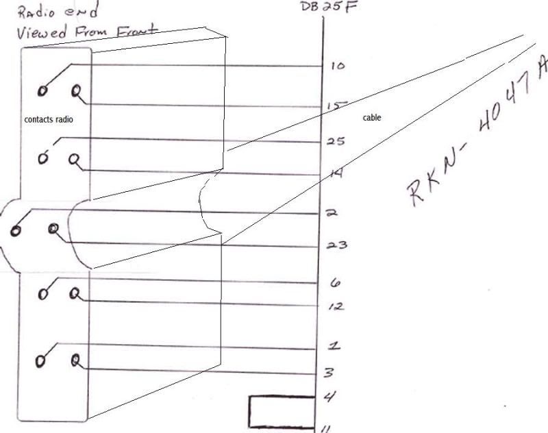
I am not sure that I have the plug vs. pin orientation correct per the drawing. When comparing the pinouts and their electrical assignments to the service manual it seemed the diagram didn't line up right and the image was of the socket on the radio if looking at it straight on (or can be described as the back of the plug).

I am hoping that some one could just simply identify a couple of the opposing corner pins at the corresponding DB25 assignment to help me get oriented here.

original drawing
Image
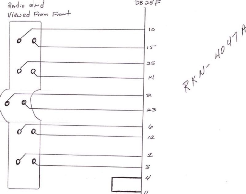
Am I looking at the original drawing in with the correct orientation?
Image
jmr061
was KB9KST
Posts: 3176
Joined: Fri Sep 14, 2001 4:00 pm

Re: Astro Spectra FLASH CABLE Diagram Question

Post by jmr061 »

The key is where it says viewed from front of the radio. Its drawn like you holding the radio end in your hand looking at the no wire input end. I had the same issue when I built mine.

If yours doesn't work flop the wires side for side on the radio end plug.

Jason
User avatar
mancow
Batboard $upporter
Posts: 2374
Joined: Sun Sep 09, 2001 4:00 pm

Re: Astro Spectra FLASH CABLE Diagram Question

Post by mancow »

I got it. I had the orientation right but I failed to connect a line.


Thanks for the reply.
Post Reply

Return to “Radio Programming”