Astro Spectra FLASH CABLE Diagram Question
Posted: Fri Apr 17, 2009 4:47 pm
I built the RKN4047A cable from the Batlabs diagramhttp://www.batlabs.com/images/rkn4047a.gif but it appears I have something incorrect. The radio eventually reverts to the FL 01/90 power fault mode and it desn't write.
I am not sure that I have the plug vs. pin orientation correct per the drawing. When comparing the pinouts and their electrical assignments to the service manual it seemed the diagram didn't line up right and the image was of the socket on the radio if looking at it straight on (or can be described as the back of the plug).
I am hoping that some one could just simply identify a couple of the opposing corner pins at the corresponding DB25 assignment to help me get oriented here.
original drawing
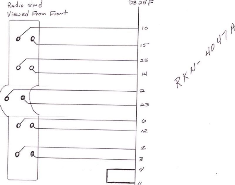
Am I looking at the original drawing in with the correct orientation?
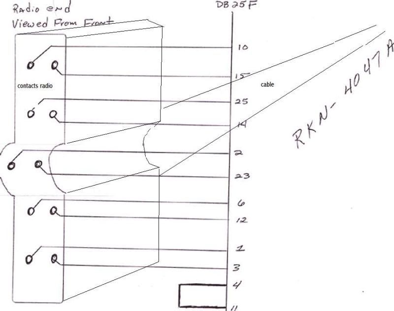
I am not sure that I have the plug vs. pin orientation correct per the drawing. When comparing the pinouts and their electrical assignments to the service manual it seemed the diagram didn't line up right and the image was of the socket on the radio if looking at it straight on (or can be described as the back of the plug).
I am hoping that some one could just simply identify a couple of the opposing corner pins at the corresponding DB25 assignment to help me get oriented here.
original drawing
Am I looking at the original drawing in with the correct orientation?